
Jet Bridge Controller PCBA: Define Interface and Interlock Evidence
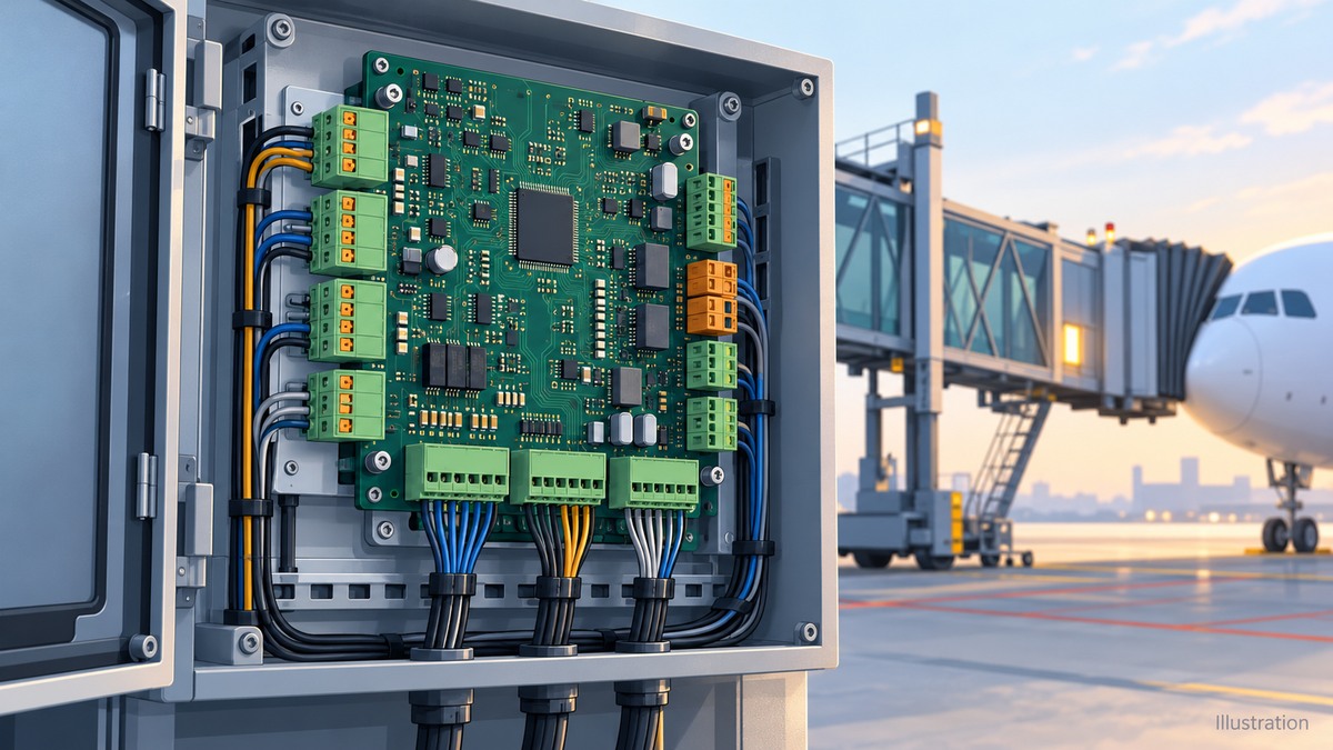
Table of Conent
Table of Conent
A jet bridge controller PCBA (printed circuit board assembly) should be released against a defined interface map, a controlled hardware and firmware configuration, and test records that demonstrate its assigned behavior. Passing optical inspection or a normal operating cycle does not establish that movement permissions, feedback faults and restart conditions behave correctly. The boarding bridge original equipment manufacturer (OEM) must define those requirements and retain responsibility for validation of the complete machine.
For procurement, the useful question is which evidence the assembly supplier will deliver, which checks require an OEM fixture, and which functions remain outside the board. Resolve those boundaries before approving the pilot build.
Define the board and safety-function boundaries
Start with the approved function specification rather than assigning a safety rating to the whole board. A controller may read operating permissions, issue a movement request, report diagnostics or communicate with another controller. A separate safety controller, contactor circuit or other protective subsystem may have a different responsibility. The architecture determines the allocation; the application name alone does not.
The Pilz explanation of EN ISO 13849-1 describes defining safety functions and their required performance before verification and validation. Apply that sequence to the release package: identify the initiating condition, required response, operating mode, interfaces and approved acceptance criteria. Do not substitute a generic performance level, response time or component grade for the OEM’s assessment.
Write an ownership statement for each relevant function. Who specifies the response? Who implements it? Who supplies the stimulus and acceptance limit? Who approves the result? Distinguish a board output entering its specified state from a physical bridge reaching a safe condition. The latter depends on equipment and interactions that a board fixture may not contain.
Keep the functional-safety evidence boundary visible in the purchase specification. Manufacturing records can establish conformity to an approved assembly definition and test plan. They do not, by themselves, establish complete-machine safety or authorize a changed safety function.
Release an interface and mode-permission map
Every command needs a defined permission context. Map the physical connector and pin to the signal’s origin, electrical interface, active interpretation and approved response in each applicable mode. Include the harness revision and destination, so a correct board cannot silently become an incorrect installation.
ADELTE’s passenger boarding bridge description provides system context involving cabin controls, programmable logic controller (PLC) control and remote operation. That context calls for clear interface ownership; it does not prove that a particular custom PCBA performs all those functions. Confirm the allocation for the actual bridge configuration.
| Interface case | Information to release | Acceptance evidence and owner |
|---|---|---|
| Movement request and permission | Command source, applicable mode, permission source and required inhibit behavior | OEM defines the permitted combinations; board test records the specified output response |
| Position or limit feedback | Sensor interface, physical reference, valid interpretation and fault handling | Fixture applies independent feedback states; OEM confirms installed sensor and mechanism behavior |
| Console or remote interface | Authority selection, communication state and behavior when authority changes or communication is lost | Interface test covers specified transitions; system integration verifies the connected controllers |
| Power and restart | Startup configuration, retained state and conditions required before a new command is accepted | Approved power-cycle sequence with output and diagnostic records, followed by system validation |
Interlocks can also cross supplier boundaries. In a specific Salt Lake City installation, an ADB SAFEGATE integration announcement describes a docking restriction when the bridge is outside a predefined parked position. Use that as an example of an interface dependency, not a universal bridge design. The release map should identify the actual external source, its interpretation and the party validating the combined behavior.
Control the board, harness and process configuration
Freeze a build identity that connects the PCB revision, bill of materials (BOM), approved substitutions, connector variants, harness definition, firmware image and test-program revision. Include the firmware loading and verification method even when software is supplied by the OEM. A successful test with an unidentified image cannot support a repeatable production release.
Once these interfaces are defined, share the interface map and assembly constraints for a review of sourcing, connector access, assembly sequence and proposed test scope. Include the items the OEM will supply, especially firmware, harness adapters and acceptance criteria, so the build review produces a clear allocation of work.
Connector selection deserves an explicit change rule. A substitute that fits the footprint may differ in keying, retention, mating compatibility or installation access. Require engineering approval where those characteristics affect the released interface. Record the approved mating part and terminal orientation, rather than relying on a catalog description or a sample assembly alone.
Specify assembly process and workmanship requirements separately from functional behavior. The IPC announcement explaining J-STD-001 and IPC-A-610 distinguishes materials and process requirements from assembly acceptance. State the contractually applicable revision and class; do not infer them from the airport application. Neither document replaces the controller’s functional requirements.
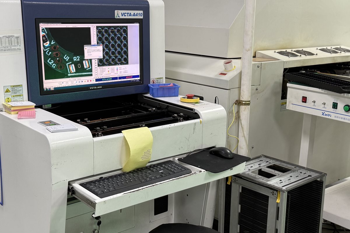
Optical inspection supports checks of visible assembly features. Electrical and functional tests need their own coverage statements, including inaccessible nodes and fixture limitations. If coating or another post-assembly operation is specified, define connector masking, test access and the verification sequence. Do not assume an inspection completed earlier covers a later process change.
The official OrinewPCB factory tour below provides general context for assembly equipment, component sourcing and through-hole work. It is not evidence of a jet bridge project or qualification. When comparing a full-turnkey PCB assembly scope, identify which operations and records are included in the actual quotation.
Use independent stimuli to expose false passes
A fixture should distinguish a commanded state from independently observed feedback. If its software derives the expected feedback directly from the issued command, it may confirm its own assumption while missing an incorrectly interpreted input. Review the stimulus and measurement paths before treating a green result as evidence.
Build a requirement-to-test record that identifies the board configuration, applied condition, measured response and acceptance rule. Use approved, electrically compatible simulators in a controlled board test setup. The following cases are planning prompts, not instructions to defeat an interlock or introduce faults on an operating bridge.
| Case | Independent fixture action | Evidence to retain |
|---|---|---|
| Permission absent | Apply a specified request while independently setting the permission input to its nonpermissive state | Observed output, reported status and response assessed against the approved requirement |
| Feedback disagrees | Set feedback independently of the commanded output, within the defined electrical test envelope | Detected mismatch and specified diagnostic or output response; no command-derived substitute |
| Reset and restart | Apply the released reset or power-cycle sequence with the specified initial input states | Startup outputs and conditions for accepting a subsequent request |
| Configuration mismatch | Present a defined incompatible or unidentified configuration through the approved test method | Identification or rejection behavior and disposition, where required by the design |
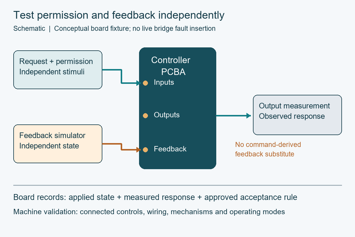
Test transitions as well as steady states when the specification requires them. An input that is present at startup can produce a different path from the same input arriving after mode selection. Identify the permitted sequence, the observation point and the specified response window in the test case. The engineer reviewing coverage should be able to distinguish an untested sequence from a passing result. Do not let fixture delays or automatic retries hide a first-response failure; preserve the initial observation and the reason for any repeat.
Check the fixture itself with a documented challenge that demonstrates it can distinguish the required states. A reference board alone may reproduce a shared configuration error. Retain fixture identity, software revision and relevant verification status alongside the unit result. Where a response depends on an external actuator or controller, document what the simulator represents and what remains untested.
Close the pilot and preserve service compatibility
Release the pilot when discrepancies have an approved disposition and the records identify exactly what was built and tested. Separate assembly defects, requirement ambiguities and fixture defects, because each requires a different corrective action. A successful retest should reference the change that resolved the failure, not erase the original result.
Keep complete-machine validation on its own approval path. Pilz’s validation description concerns checking implemented protective measures. Board records contribute evidence, while installed wiring, mechanisms, connected controllers and operating modes still need the applicable system-level checks.
Make retest scope part of change approval. A connector substitution may require mating and assembly-access review, while a firmware change may require different transition cases. State which existing results remain applicable, which cases must run again and who accepts that judgment. This keeps a limited manufacturing change from becoming an undocumented change to the controller behavior.
For service replacements, maintain an approved compatibility matrix linking board, firmware, harness and bridge configuration. Define who approves a substitution and when changed interfaces or behavior require renewed testing. Physical interchangeability alone is insufficient evidence for releasing a replacement into the fleet.
A useful quotation depends on an identifiable configuration and clear acceptance responsibilities. For that review, provide the released controller build package with fabrication data, BOM, placement data, assembly drawings, build quantity, firmware handling instructions, interface map and test requirements. These inputs let the review align fabrication, sourcing, assembly and pilot acceptance with the OEM’s release plan.
Latest Blog



Contact Info
Phone: +86-755-82882936
Email: [email protected]
WhatsApp: +86-13570802455
Wechat: +86-13570802455
Address: 2nd floor,D Bldg.,Electric Link Technology Bldg.,Gongming,Guangming New Dist.,518106 Shenzhen, China