
Runway Lighting Controller PCBA: Qualify SMT and Through-Hole Assembly
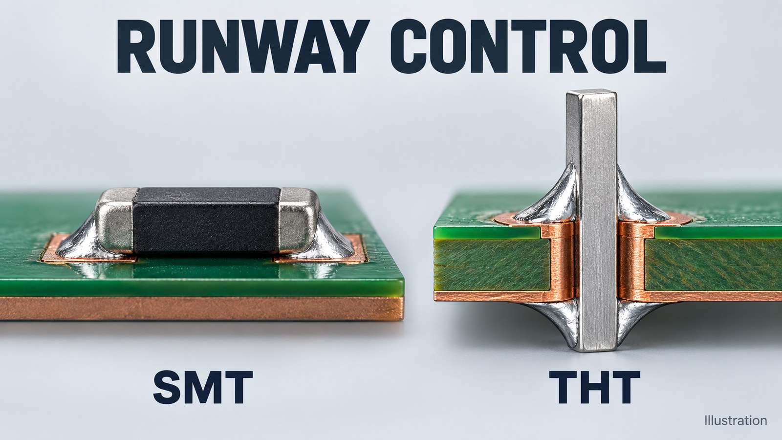
Table of Conent
Table of Conent
A runway lighting controller PCBA should enter a mixed SMT and through-hole build only after the OEM defines the board’s actual interfaces, approved component processes, and acceptance evidence. Use surface-mount technology (SMT) where the design calls for it; qualify a separate soldering route for through-hole technology (THT) parts unless their exact manufacturer part numbers are approved for through-hole reflow (THR). Preserve inspection and fixture access through every assembly stage.
The manufacturing decision extends beyond getting solder into a hole. A controller may issue commands to a constant current regulator (CCR), receive status signals, or perform another defined monitoring function. Do not assume its PCB carries the lighting series-circuit power. Release the electrical boundary, component restrictions, and separate command and status checks with the assembly package.
Define the controller-to-equipment boundary
Identify what the board controls and what it observes before assigning connector ratings, isolation requirements, or production tests. The equipment name alone does not identify the electrical stress at a PCB terminal.
The FAA lists AC 150/5345-10H as the active specification for CCRs and regulator monitors. Its separate AC 150/5345-56B addresses the L-890 Airport Lighting Control and Monitoring System (ALCMS). These equipment and system scopes help define the handoff; neither makes a generic assembled board an approved airfield product. Status checked October 28, 2026.
For each connector, record the signal owner, voltage and current range, reference or isolation arrangement, mating harness, and required response. Separate command outputs, status inputs, communication, auxiliary power, and any actual measurement connections. If the design includes a power or current-sensing path, identify its circuit and approved insulation basis explicitly. Do not copy a series-loop current or a regulator’s output voltage into a controller-PCB requirement without that circuit evidence.
Make this interface list part of the assembly drawing and test specification. It prevents an assembler from treating two visually similar connector variants as interchangeable, or a fixture designer from measuring a command output when the requirement concerns independent equipment status.
Qualify the soldering route for each exact part
A through-hole footprint permits an insertion geometry; it does not grant reflow compatibility. Approve the process from the exact component’s thermal, flux, cleaning, and mechanical requirements, then confirm that the complete board can follow that route.
Phoenix Contact’s PCB assembly guidance distinguishes THR from conventional THT assembly. THR integrates suitable through-hole connections into a reflow process. That makes a qualified THR connector a candidate for shared processing, not evidence that an ordinary terminal block, relay, or transformer can withstand the same profile.
| Part group, if present | Decision to close | Required release evidence |
|---|---|---|
| SMT controller, interface ICs, and passives | Qualified reflow exposure and board support | Exact part restrictions, handling requirements, approved profile, and inspection program |
| THR-qualified connector | Whether pin-in-paste fits the approved construction | Manufacturer process permission, hole/pin geometry, paste-volume plan, and joint inspection |
| Conventional THT connector or terminal block | Selective, wave, or controlled hand soldering as appropriate | Part-specific exposure limits, access, support, solder-side joint map, and acceptance criteria |
| Electromechanical relay | Soldering and cleaning route compatible with its enclosure | Exact relay type, flux/cleaning restrictions, cooling instructions, and any approved venting step |
| Heavy or heat-sensitive component | Installation order and allowable heat/mechanical load | Mounting instructions, retention or support, process limits, and post-installation access |
Evaluate the sequence against the actual layout. A tall connector can obstruct inspection of nearby SMT joints; a large copper connection can need a different heat input from a small signal pin. A process that produces one acceptable sample is insufficient evidence for an uncontrolled production instruction. Define the qualified parameters, tooling revision, inspection method, and conditions that reopen approval.
Use a selective-solder joint map to connect the intended joints with nozzle or tool access, nearby component restrictions, and the chosen board support. Specify relevant keepouts on controlled drawings. Avoid a generic clearance or soldering temperature that ignores the component, machine, and board construction.
Once the part restrictions are collected, share the mixed-assembly constraints and joint map with the BOM, assembly files, and quantity so the proposed soldering route, tooling, and inspection scope can be checked before quotation.
Inspect each joint while access remains available
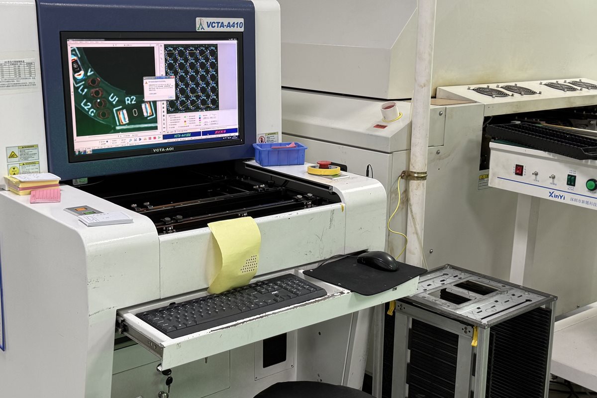
Place inspection gates where they can observe the joints actually created at that stage. An SMT optical pass does not accept through-hole joints installed later, and a later connector can hide a defect that was previously accessible.
Review the assembly traveler from both sides of the board. Identify which joints are visible after reflow, which require another viewing angle or agreed method, and which become obscured after THT insertion, brackets, harnesses, or protective material. Give each group its applicable workmanship criteria and repair disposition. Record the as-built revision and inspection program so a report cannot silently refer to a different variant.
Cleaning also needs a part-specific decision. TE Connectivity’s relay mounting and cleaning guidance warns against flux entering relay components and distinguishes open or dust-covered relays from plastic-sealed types. A cleaning instruction appropriate for one enclosure is not automatically appropriate for another. Follow the exact part and approved process rather than assuming every populated board can be immersed.
Keep connector mating surfaces, programming access, inspection points, and any specified insulation features accessible through the required gates. Where coating is required by the design, release its preparation, masking, cure, and retest requirements separately. Do not infer a coating requirement or an environmental rating merely because the equipment serves an airport.
Test command and status paths independently
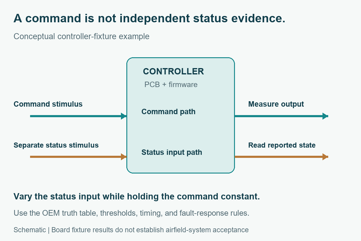
A production fixture should demonstrate each assigned board function using its specified stimulus and observation. Commanding an output and reading the same commanded value back from firmware does not establish that an independent status-input path works.
As an engineering example, a board may have a command output and a separate status input from external equipment. Exercise the output against an approved representative load. Then vary the status-input stimulus while holding the command constant, and check the reported state against the OEM truth table. Add disagreement, disconnected input, restart, and communication-loss cases only where the design specifies the expected behavior. The OEM must supply thresholds, timing limits, and fault-response rules; the assembler should not invent a universal “safe” state.
| Question | Suitable evidence to define | What it does not establish by itself |
|---|---|---|
| Were the specified joints assembled acceptably? | Applicable inspection and repair records | Correct firmware behavior or an external lighting state |
| Does the command output meet its board requirement? | Measured output under the specified fixture load | Operation of the installed CCR, harness, or lighting circuit |
| Does the status path recognize independent input states? | Separate input stimulus and recorded response against the truth table | Accuracy of an external sensor or complete monitoring chain |
| Does the integrated airfield system perform correctly? | Equipment/system test evidence owned by the responsible integrator | Acceptance of every production unit’s soldering and configuration |
For a multi-channel design, check channel identity as well as the expected output value. Exercise one channel while the other commands remain fixed and observe the specified outputs and status mapping. This can expose swapped connector assignments or unintended channel coupling that a repeated single-channel test would miss. Use the actual permitted combinations from the OEM test specification.
This distinction is consistent with the scale of the FAA ALCMS specification’s Section 10.2 test system, which includes actual control equipment and lighting loads. A board fixture is a defined subset of that evidence, not a substitute for the integrated system. The table above is an engineering allocation framework, not an FAA certification checklist.
Build the requirement-to-test record around the board revision, firmware identifier, fixture and limit-set revisions, unit identity, actual result, and disposition. State who develops the fixture and who approves its coverage before the pilot lot begins.
Release the board as a controlled equipment configuration
A repeatable build requires one approved board, component, firmware, and test baseline. Preserve that identity when purchasing alternatives, repairing a unit, or moving work between assembly stages.
Provide fabrication data, the approved stackup and material restrictions, exact-MPN BOM and alternate rules, placement data, assembly drawings, soldering restrictions, and connector orientation. Include firmware/configuration instructions where applicable, the joint map, inspection criteria, fixture specification, and any cleaning or coating requirements. Record which equipment-level requirements remain outside the PCBA supplier’s acceptance scope.
When evaluating a full-turnkey PCB assembly scope, separate component procurement and assembly from fixture development and system qualification. A quote should identify supplied tooling, reusable setup, approved parts, first-article evidence, recurring tests, and customer approval holds. Confirm capability for the actual package instead of treating a service description as approval of every airfield configuration.
Close a first-article review against this baseline before releasing repeated lots. Reassess a connector, relay, soldering-route, or firmware change against the affected interfaces and tests. The practical release gate is agreement between the component process permissions, inspectable workmanship, independently exercised control/status functions, and controlled records.
For a complete PCBA build, provide the released board, BOM, and acceptance package with quantities, approved alternatives, test responsibilities, and delivery requirements. OrinewPCB can then review the fabrication, sourcing, assembly, and test scope against the same configuration before quotation.
Latest Blog


Contact Info
Phone: +86-755-82882936
Email: [email protected]
WhatsApp: +86-13570802455
Wechat: +86-13570802455
Address: 2nd floor,D Bldg.,Electric Link Technology Bldg.,Gongming,Guangming New Dist.,518106 Shenzhen, China