
TCAS Processor Manufacturing: Coordinate PCBA and Aircraft Box Build
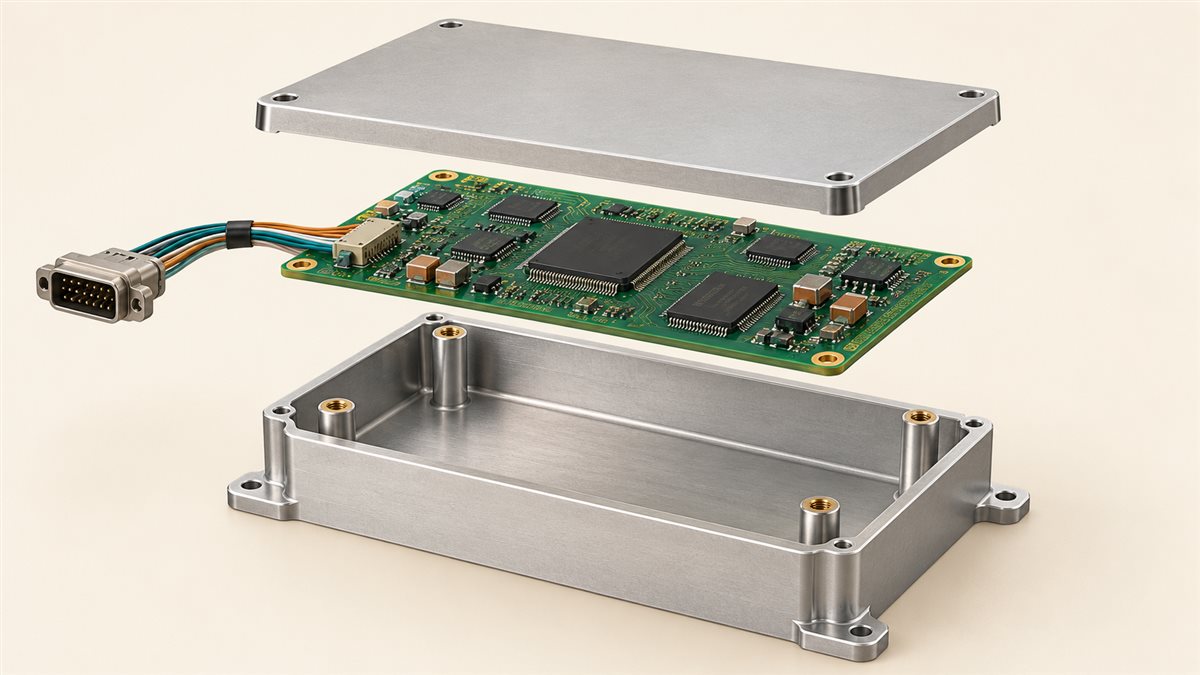
Table of Conent
Table of Conent
A TCAS processor board should enter an EMS box-build program only after the OEM identifies the released PCB assembly, loaded configuration, enclosure, harness interfaces, and acceptance evidence as one controlled equipment configuration. A board that passes solder inspection can still fail at the equipment boundary because of a connector mismatch, an unapproved software load, a mechanical interference, or an incomplete test record. The contract manufacturer can assemble and document the specified build; the design and airworthiness decisions remain with the responsible approval holder. The practical first step is a cross-referenced release package, followed by separate board, integrated-box, and OEM system-level acceptance gates.
The FAA describes TCAS as an airborne collision-avoidance function and distinguishes TCAS I traffic advisories from TCAS II, which also provides resolution advisories. The exact computer, display, transponder, antenna, and aircraft interfaces depend on the approved installation, so a generic PCBA cannot be treated as an interchangeable “TCAS board.” See the FAA’s ACAS overview and Introduction to TCAS II, version 7.1 for the functional and installation context.
Define the processor boundary before ordering a board
The processor PCBA is one element of an equipment and aircraft installation, so the purchase order must identify which interfaces the EMS supplier builds and which the OEM integrates. Depending on the design, the processor may exchange information with a Mode S transponder, aircraft data sources, displays, antennas, or other avionics. The FAA’s TCAS II booklet describes those relationships; it does not prescribe one PCB layout or one set of connectors for every supplier. A sourcing specification should therefore reference the OEM’s interface-control document and approved bill of materials rather than infer a connection from a product label.
Confirm whether the contract scope is bare-board fabrication, populated PCBA, conformal coating, enclosure integration, harness installation, test-fixture execution, or shipment of a complete unit. If the buyer requests a “box build” without defining the boundary, the supplier may price a finished enclosure while the OEM expects a serialized, loaded, tested unit. Our separate Mode S sourcing guide addresses approved-source and component-change risks; those controls matter here, but they do not replace the TCAS processor’s configuration and integrated-equipment requirements.
Release one configuration package for PCBA and enclosure work
A usable handoff maps each physical and digital deliverable to a revision, acceptance method, and decision owner. This matrix is a planning example; the OEM’s approved data and contract determine the actual required records.
| Deliverable | Release question | Evidence at handoff | Decision owner |
|---|---|---|---|
| PCBA and components | Which drawing, BOM and approved alternates apply? | PCB/assembly revision, approved MPN list, placement files, lot or serial traceability | OEM engineering and purchasing |
| Loaded software or programmable configuration | Which approved image and programming method match this hardware revision? | Version/hash or other OEM-defined identifier, programming log, readback result | OEM design authority; EMS executes released method |
| Enclosure, hardware and thermal interface | Do standoffs, clearances, fasteners, grounding and heat paths match the board? | Mechanical drawing, torque/process instructions, fit and continuity record | OEM mechanical/electrical engineering |
| Harness and external connectors | Are pinout, keying, shielding and strain relief defined at both ends? | Interface-control drawing, harness revision, continuity or wiring test | OEM systems engineering; EMS builds to release |
| Acceptance and serialized unit record | Which checks release the board, box and final equipment? | Controlled test procedure, limits, unit serial, deviations and disposition | OEM quality/design authority, as contractually assigned |
The most expensive omission is often a version mismatch, not an obviously missing file. For example, a revised connector drawing with an unchanged harness build sheet can pass a PCBA electrical test yet prevent box closure. Require the released package to identify its cross-document revision set and a named owner for any discrepancy. A generic controller box-build acceptance example shows why mechanical and electrical acceptance need separate evidence, although its application is different from avionics.
Check fit, bonding and interfaces before committing to volume
The first integrated build should prove that the released board can be mounted, connected, and serviced in the released enclosure without rework. Review standoff height and hole alignment, connector mating envelope, harness bend radius and strain relief, chassis bonding points, keep-out zones, fastener access, and any OEM-defined thermal contact. These are design-dependent checks: the supplier should measure against drawings and agreed limits, not claim that a photograph alone demonstrates compliance.
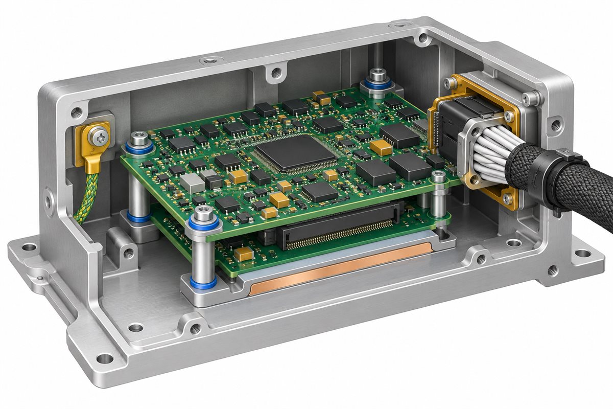
A pilot unit can expose whether the enclosure or harness needs an engineering change. If it does, stop and route the change through the OEM’s configuration process before using the revised item on production units. Substituting a shorter standoff or moving a ground lead on the shop floor may make the lid close, but it changes the build basis and may invalidate the test method.
For a project at this point, provide the PCB/assembly revision, controlled BOM, mechanical drawings, harness pinout, pilot quantity and proposed test scope through the assembly package review form. The useful output is a scope and manufacturability discussion with explicit open questions before a production quotation, including which acceptance steps the OEM will supply or retain.
Separate process inspection from equipment qualification
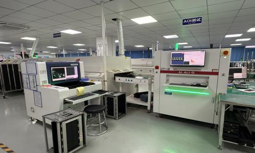
AOI, electrical tests and workmanship records can support the PCBA build record, but they do not establish that a TCAS processor meets its equipment-level functions or aircraft installation requirements. Define distinct release gates so each result answers the correct question.
| Gate | Typical question and evidence | Release decision |
|---|---|---|
| Board / process | Were the specified materials placed and assembled to the released process? Inspection, traceability and any OEM-defined board test. | Accept or quarantine the PCBA against the contract criteria; do not infer TCAS function. |
| Integrated box | Do the released board, enclosure, harness and loaded configuration fit and connect? Fit, continuity, bonding and OEM-defined functional fixture records. | Accept the built unit for the next OEM-defined gate; record unit serial and configuration. |
| Equipment / installation | Does the approved TCAS equipment and installation meet the applicable system and environmental requirements? OEM-controlled plans and results. | Approval holder determines conformity and disposition; an EMS inspection report alone is insufficient. |
Environmental methods must also be selected from the actual equipment and installation requirements. RTCA DO-160 describes airborne-equipment environmental test procedures; it is not a license to assume that every processor board receives every test or that a factory visual check substitutes for qualification. Our environmental test selection guide can help frame questions for a buyer, while the OEM controls the specific qualification plan. FAA AC 20-151C provides guidance for TCAS II and Mode S transponder airworthiness approval; applicability and latest revisions should be confirmed for the program.
Bind changes and test results to each serialized unit
Traceability is useful only if it can reconstruct what was built and which deviations were approved. For each unit, associate the serial with the PCB and assembly revisions, critical component lots where specified, programmed configuration identifier, enclosure/harness revisions, test-procedure version, results, and authorized dispositions. Agree on record format and retention in the purchase contract. A spreadsheet of pass/fail cells with no procedure version cannot show whether two units were tested to the same limits.
When a PCN, end-of-life notice or workmanship issue affects a part, bound the affected population by BOM line, MPN, lot/date and serial. The EMS supplier can flag affected material and propose a mitigation; the OEM must decide whether an alternate, rework, retest or design change is acceptable under its controlled program. This distinction is consistent with the FAA’s AC 20-152A guidance on assurance of electronic hardware, while the applicable certification basis remains program-specific.
Send a quotable package and name the open decisions
For a credible EMS proposal, send the released fabrication and assembly data, approved BOM and alternates, component-supply responsibility, programming method, enclosure and harness drawings, pilot/production quantities, acceptance criteria, test-fixture ownership, record requirements, and packaging or handling constraints. Mark any open engineering decision as open; a quote should state assumptions rather than silently decide an interface or test limit. A PCB assembly and box-build scope can cover multiple manufacturing steps, but only the contracted and verified steps should appear in this TCAS program’s statement of work.
Ask the supplier to split recurring unit cost from nonrecurring fixture, programming, documentation and pilot-build work. This exposes a common buying tradeoff: a lower assembly price can hide costly integration or evidence work. It also gives engineering a clear point to reject a substitute component or an undefined box-level test before volume material is committed.
Close the board-to-box gap before production release
The reliable sequence is to freeze the cross-referenced configuration, prove a pilot unit’s board-to-box interfaces, record separate PCBA and integrated-unit acceptance, then let the OEM close the equipment and installation requirements. This prevents a workmanship pass from being mistaken for an avionics approval and keeps design changes visible to the people who own them.
When the controlled package and acceptance ownership are ready, send the revisions, quantities, enclosure/harness data and required evidence through the project scope submission. The next useful step is an engineering review of buildability, missing data and test responsibility before a production quote is finalized.
Latest Blog

Contact Info
Phone: +86-755-82882936
Email: [email protected]
WhatsApp: +86-13570802455
Wechat: +86-13570802455
Address: 2nd floor,D Bldg.,Electric Link Technology Bldg.,Gongming,Guangming New Dist.,518106 Shenzhen, China