
Industrial Ethernet PCB: Release the PHY-to-Port Path for Production
Table of Conent
Table of Conent
An industrial Ethernet PCB is ready for production when the OEM has released a complete port definition, not just a routed differential pair. Specify the speed and media, MAC-to-PHY interface, PHY part and configuration, isolation magnetics, connector, shield and chassis treatment, power and clock sources, and the test evidence expected for each populated port. Then review the stackup and the signal path against the selected device and magnetics documentation. A successful link LED is useful, but it does not prove the intended mode, programmed identity, packet path, EMC behavior, or application protocol. Fabrication and assembly suppliers can build and screen the approved hardware; the equipment owner must define the network and environmental acceptance criteria. The practical release is one controlled package linking the schematic, layout, BOM, software configuration, port variants and production test recipe. This prevents a board from passing a generic continuity check while shipping with the wrong PHY straps or an unverified external interface.
Define the port before drawing PHY traces
Start with a port contract that names what the assembled equipment must do. A 100BASE-TX service port, a Gigabit machine controller and a single-pair Ethernet sensor interface need different PHYs, magnetics, connectors, cable assumptions and tests. “Industrial Ethernet” describes an application setting; it does not itself define a data rate, an industrial protocol, a redundant topology or an immunity level.
For each physical port, record the selected media and speed, the host interface (such as RMII or RGMII), the PHY manufacturer part number and revision, the magnetic component or integrated connector, the external connector pinout, shield termination, permitted power-over-cable arrangement if any, cable type and expected link partner. Record whether the unit is an endpoint, a two-port device or part of a switch. The ADI ADIN1300 product information illustrates why a named PHY matters: its interface choices, power domains, strap options and diagnostics are device-specific. They cannot be transferred unchanged to another PHY.
Set a second boundary around system behavior. Time synchronization, redundancy and protocol conformance depend on software, network topology and external equipment as well as the PCB. A fabricator can verify released copper and an assembler can run an approved board test; neither should infer a system-level timing or protocol claim from a working connector. The port contract becomes the reference for the schematic, layout, purchasing alternates and test fixture.
Route the MAC, PHY, magnetics and cable path as separate interfaces
Review the signal chain in order: MAC or host bus, PHY, media-dependent interface (MDI), isolation magnetics, connector and cable. Each transition has a different electrical or mechanical question. For example, the host-to-PHY bus needs an agreed clock and timing budget, while the MDI pairs need the specified impedance, pair assignment, controlled return path and minimal discontinuities. The transformer and shield boundary introduce isolation and chassis decisions that cannot be settled by matching trace lengths alone.
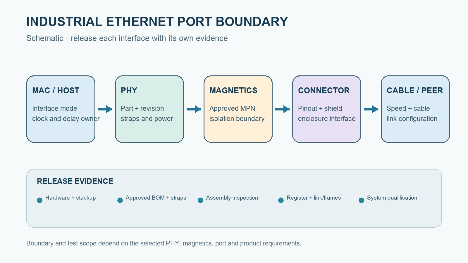
The ADI ADIN1300/ADIN1200 layout guide recommends a continuous reference under relevant signal routing, short paths to the magnetics, local decoupling, and deliberate separation between chassis and PHY ground for its devices. The TI Ethernet PHY PCB layout checklist likewise treats MDI routing, magnetics keep-out, return vias, ESD placement and ground treatment as related checks. These are design references, not universal manufacturing tolerances. Freeze the actual stackup with the board supplier and apply the selected PHY, magnetics and connector data sheets to the released revision.
Keep the route review tied to the full channel. A nominal differential impedance on a coupon does not by itself verify an assembled connector, a soldered transformer, a shield transition or a cable. Conversely, a short link on a lab bench cannot prove that the stackup and MDI geometry meet the released drawing. The high-speed PCB transmission-line guide explains why edge rate and return path, rather than a generic “high-speed” label, drive routing care.
Keep clock, power and chassis decisions attached to the selected device
Clocks, straps, reset and supply rails can silently change an Ethernet port even when the copper pairs are correct. Identify the reference-clock source, frequency, startup relationship, power domains, decoupling and reset sequence from the chosen PHY documentation. Record which host or PHY inserts any RGMII clock delay; double insertion and missing delay are distinct failure modes. Capture the strap resistor population and the register state expected after startup, including PHY address, interface mode and advertised link behavior where applicable.
Do not copy a grounding or termination drawing across different magnetic modules or power-over-Ethernet variants. The shield-to-chassis path, center-tap treatment, ESD protection and isolation geometry require the actual connector and magnetics schematic plus the product’s EMC and safety requirements. The Würth Elektronik Gigabit front-end reference design is useful as a documented component-level example; it is not a blanket rule for a different PHY, connector or enclosure.
For fabrication, identify controlled nets and the stackup revision rather than asking for “Ethernet impedance” without a tolerance or measurement plan. The impedance-controlled PCB RFQ guide shows how to state net classes, the proposed stackup and acceptance evidence. Where the routing is controlled, the controlled-impedance fabrication scope provides a relevant service path, subject to review of the actual design and available build options.
A design review should also check the release files against the physical enclosure. The connector opening, board thickness, shield fingers, cable direction and assembly access can force a placement change after signal routing appears complete. If these choices are still open, share the port map and stackup for manufacturing review with the schematic, connector drawing and intended build quantity so the fabrication and assembly assumptions can be assessed together.
Release one port-by-port fabrication and assembly matrix
A port matrix prevents a correct schematic from being paired with the wrong BOM, stackup, firmware or fixture recipe. Give every populated port a stable identifier and revision-controlled row. Variants should name the approved alternative rather than leaving an unpopulated connector, a substituted PHY or an optional magnetic component to interpretation on the shop floor.
| Release item | OEM decision | Build control | Evidence to retain |
|---|---|---|---|
| Host-to-PHY interface | Mode, voltage, clock source and delay owner for each port | PHY revision, strap population, clock and reset components | Schematic/firmware revision and startup register readback |
| MDI and magnetics | Pair assignment, stackup, impedance class, magnetic MPN and permitted alternate | Controlled layout files, orientation, footprint and assembly drawing | Fabrication checks, inspection record and specified port test |
| External boundary | Connector, shield, chassis, protection, cable and any power-over-cable scope | Approved connector/protection parts and enclosure interface | Mechanical inspection plus project-defined electrical or EMC validation |
| Identity and software | MAC-address ownership, image/revision and port configuration | Programming and duplicate-prevention process | Readback tied to board serial or lot and test recipe |
The matrix does not substitute for Gerbers or ODB++, a BOM, pick-and-place data, assembly drawings and a controlled test procedure. It tells suppliers how those files relate and which changes require re-review. A PHY alternate may alter pinout, supply, straps, clocking, driver settings or diagnostics. A magnetics alternate can affect insertion loss, isolation and chassis behavior. If an alternative is needed, engineering should approve the effectivity and the affected validation before purchasing or assembly treats it as interchangeable.
Keep board-fabrication evidence distinct from assembled-port evidence. A continuity or impedance result can support the fabricated interconnect, but it cannot establish the programmed PHY state. An AOI or visual result can support component presence and solder condition, but it cannot prove frames cross a production cable. This separation makes supplier quotations comparable because every bidder sees the same deliverable and test scope.
Prove the approved port configuration in production
Define production screening around the released port contract, not around one link LED. A fixture can power the board safely, identify the hardware variant, read critical PHY registers, confirm the requested and negotiated speed with a known peer, and send/receive a specified frame set. Record the PHY address and key strap-derived modes, software image, MAC identity where programmed, cable or adapter, peer, fixture revision, and the actual result for each populated port.
The TI DP83867 troubleshooting guide distinguishes loopback modes and PRBS paths that exercise different parts of a device. An internal digital loopback may help localize a PHY or host fault, but it does not automatically cover magnetics, the connector and the external cable. The chosen device must support the selected diagnostic; test instructions must identify the mode, expected readback and pass/fail condition. A known link partner and traffic test are useful, but product engineering still owns any specified packet-error, reconnect or latency limit.
| Layer | Typical release evidence | Useful conclusion | Does not prove |
|---|---|---|---|
| Bare-board fabrication | Netlist electrical test and specified impedance/coupon evidence | Released interconnect and measured transmission-line class | PHY configuration or assembled connector performance |
| Assembly inspection | Approved MPNs, orientation, solder and shield-joint inspection | Physical population matches the released variant | Traffic, EMC or protocol conformance |
| Powered port screen | Register readback, link mode and defined frame/loopback result per port | Selected hardware and programming operate under the fixture conditions | Every cable, environment or system-level timing case |
| Product validation | OEM-defined EMC, temperature, cable, protocol and topology test plan | Equipment behavior under the approved product conditions | Automatic coverage of a changed PCB, PHY or firmware revision |
The PCB impedance-testing guide helps distinguish a coupon measurement from a field-port functional result. Set traceability before production: which board revision, PHY and magnetic lot, software build and fixture revision generated a specific record? If the fixture reports only “pass,” a later link failure becomes harder to isolate to copper, assembly, configuration or test setup.
Separate manufacturing screening from system qualification
Production testing should be repeatable on every approved build variant; product qualification should exercise the full equipment context. EMC, ESD, surge, temperature, long-cable margin, time synchronization and industrial-protocol conformance require defined equipment, limits and test methods. They are not implied by the word “industrial,” by a component data sheet, or by a factory link test. State which checks belong to the contract manufacturer, which require a specialized laboratory, and which remain with the equipment OEM.
Before an RFQ, release the port matrix, fabrication package and stackup, BOM with approved alternates, placement and assembly drawings, firmware and MAC-address rules, fixture interface, proposed port-test steps, quantities and required records. The full-turnkey PCB assembly scope is relevant when board fabrication, component sourcing and assembly need to be reviewed as one deliverable; any test or programming requirement should be explicitly agreed for this project rather than assumed from a service label.
The actionable rule is to keep the physical port, its programmed configuration and its evidence on the same controlled revision. If that package is ready, send the controlled board, BOM, and port-test package with the expected build quantity and acceptance conditions so the board, sourcing, assembly and specified test scope can be assessed together. Keep system EMC and protocol qualification under the equipment owner’s approved plan.
Latest Blog

Contact Info
Phone: +86-755-82882936
Email: [email protected]
WhatsApp: +86-13570802455
Wechat: +86-13570802455
Address: 2nd floor,D Bldg.,Electric Link Technology Bldg.,Gongming,Guangming New Dist.,518106 Shenzhen, China