
Hearing Aid PCB Design: Balance HDI, DSP, and Battery Life
Table of Conent
Table of Conent
A hearing aid PCB is ready for fabrication and assembly only when its miniature electrical design has been reconciled with the enclosure, acoustic openings, battery, radio and production-test plan. Choose the device architecture and power source first; then reserve physical space and keep-outs for microphones, receiver, antenna, charging contacts and service access. HDI and rigid-flex construction can recover area, but a finer trace or another microvia does not solve an obstructed microphone port or an untestable battery connection. Specify current and audio behavior in listening, streaming, idle and charging states, using the selected component data sheets and an approved firmware build. Release a controlled stackup, approved parts, assembly drawings and fixture procedure together. The PCB supplier can document the interconnect, the assembler can screen the populated board, and the hearing-aid OEM must validate acoustic performance and applicable device requirements. That division of evidence makes a small design manufacturable without treating a board-level pass as a finished-device claim.
Freeze the physical and acoustic envelope before selecting HDI
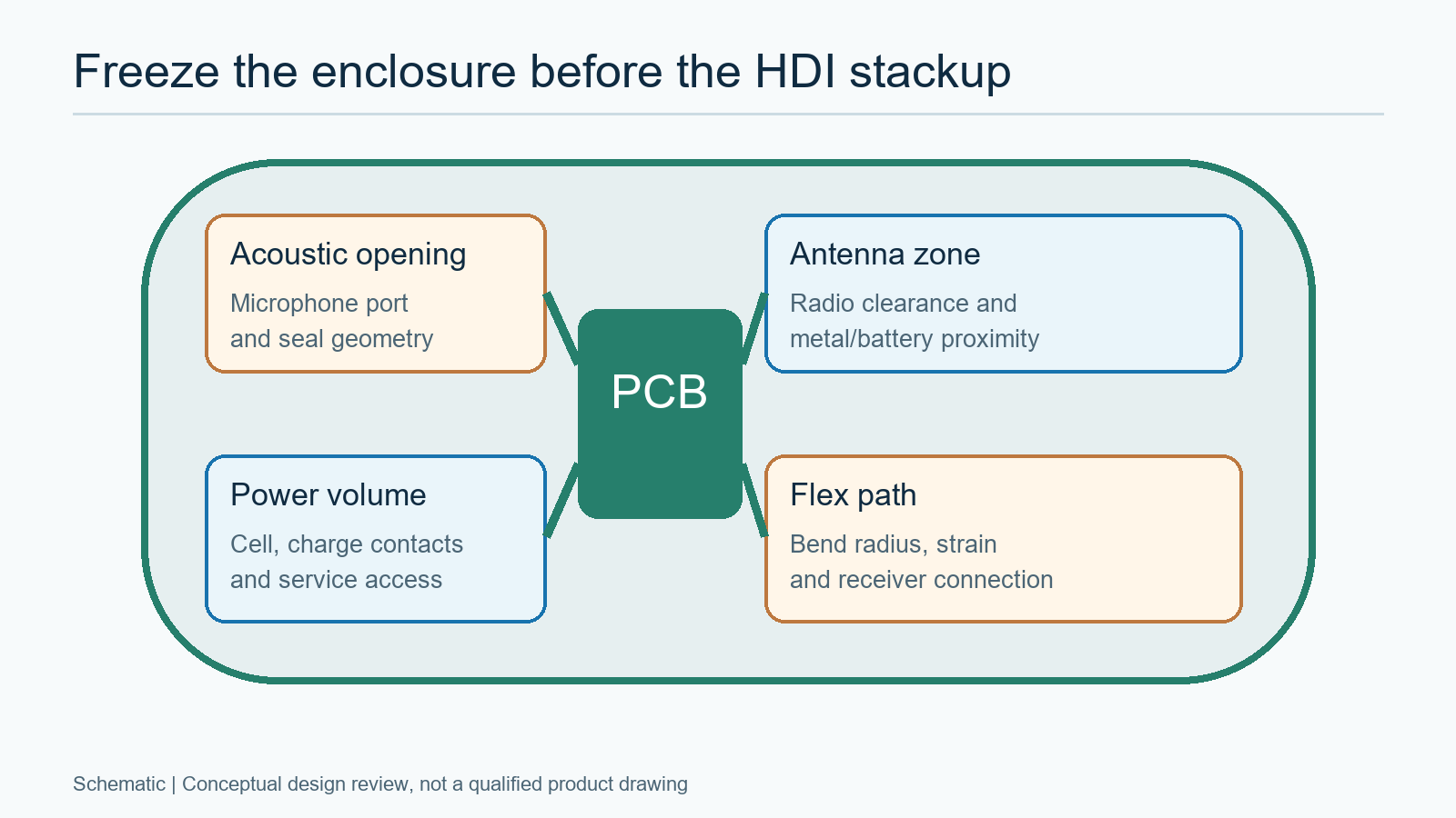
The enclosure drawing, not an attractive PCB outline, is the first constraint. Record the target shell variant, allowed board volume and thickness, battery geometry, microphone and receiver locations, charging or programming contacts, antenna zone, and the path by which a flex section must bend. Include tolerances for the shell, component height and assembly placement. A board that fits one nominal CAD cavity can still interfere with a seal, vent or production insertion tool.
Microphone placement is especially sensitive because sound must reach the port through a defined opening. The Analog Devices MEMS microphone design note explains that the acoustic hole is part of the package’s functional path. The exact port side, mounting land pattern and gasket or mesh arrangement come from the selected microphone and product acoustic design. Do not put a convenient via, adhesive bead or support rib in that path merely to shorten a route. The board supplier should receive the relevant keep-out and drill information, while the OEM verifies the final enclosure response.
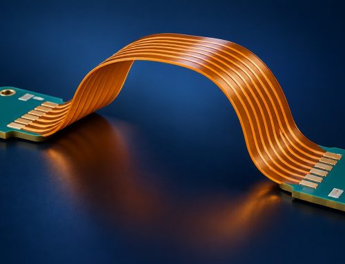
Use HDI where it answers a documented escape or area constraint. For example, a fine-pitch chip-scale package may need microvias and an approved buildup sequence; the actual pad, via-in-pad and fill requirements must follow its manufacturer package data and the fabricator’s process window. A rigid-flex design may remove a connector and reach a curved cavity, but it introduces controlled bend direction, radius, stiffener and assembly support decisions. The HDI escape release guide provides a useful handoff checklist for fine-pitch packages, while the flex and rigid-flex evidence guide separates flexible-board specifications from an assumed device qualification. Both are related manufacturing references; neither supplies hearing-aid acoustic limits.
Make one mechanical-electrical interface document with the shell revision, 3D step model, board outline, flex bend zone, microphone port, keep-outs, battery contact envelope and allowed component heights. Mark which dimensions are controlled by the OEM and which require a fabricator or assembler capability review. This step avoids paying for an elaborate HDI stackup before discovering that the real obstruction is a connector, a seal or the battery.
Choose the DSP, microphone and radio architecture as one system
Choose parts against the approved feature set, not by the smallest package dimension alone. A hearing-aid SoC may combine audio processing, radio and memory, or the design may distribute those functions across devices. The NXP NXH2004 product information is one concrete example: it describes a compact WLCSP device with dual audio DSP, wireless functions and digital-microphone support. Its characteristics illustrate the integration choice, not a recommendation that every hearing aid use that part. A different OEM architecture can have different clock, microphone-interface, RF and power requirements.
Trace the complete signal path from microphone port to digital processing and receiver. Decide whether the chosen microphones are analog or digital, how their clock and data lines are routed, where power filtering and references sit, and how production will identify a reversed or missing unit. The Analog Devices discussion of MEMS microphones in hearing aids emphasizes size, power, noise and repeatability tradeoffs. These are part-specific and device-level considerations; a generic PCBA visual inspection cannot establish a final acoustic noise floor.
For wireless designs, reserve the antenna and matching network early. Battery metal, receiver hardware, the shell and a charging coil can change the installed radio environment. Keep the radio layout and its ground clearance tied to the chosen chipset reference design, then schedule tuning and validation in the actual enclosure. The board manufacturer can produce the released copper and dielectric structure; it cannot infer over-the-air performance from a bare-board electrical test. The any-layer HDI review is useful when escape density is genuinely driving the board architecture, but a denser buildup must be justified against yield, cost and revision risk.
Before approving the BOM, record which DSP configuration, microphone part, receiver and radio matching parts define each product variant. State permitted substitutions and the evidence needed to accept them. A footprint-compatible microphone can differ in port geometry or electrical behavior; a nominally similar battery can change thickness, connector pressure or charging constraints. Treat those as engineering change decisions, not purchasing discretion.
Build a measured power budget for listening and streaming states
Battery life is a mode-and-duty-cycle result. A single quoted processor current cannot predict operating time when microphones, audio DSP, radio, receiver drive, regulators and charging circuits behave differently across use states. The NXP hearing-aid application overview distinguishes zinc-air and rechargeable Li-ion architectures, with different power-management implications. Choose the actual battery chemistry and approved protection/charging architecture before the PCB power tree is frozen.
Make a power table for the exact firmware and hardware revision. Measure or obtain justified estimates for listening, wireless streaming, idle/storage and charging states, with supply voltage, temperature and volume or receiver-load conditions documented. Record transitions and wake behavior, not just steady-state averages. A regulator that looks efficient at peak load may be a poor fit for long low-current periods; a radio burst may create droop that a bench supply hides. Product engineering owns the use profile and battery-life target; the assembler can run defined board-level current screens when limits and a fixture are supplied.
| Decision | Evidence to provide | Manufacturing consequence | Owner of final limit |
|---|---|---|---|
| Battery and charging | Chemistry, envelope, contact/coil position, safe test states | Power-tree components, board height, fixture access | OEM product and battery engineering |
| DSP and microphone path | Approved MPNs, port geometry, firmware and audio interface | Fine-pitch escape, acoustic keep-outs, assembly orientation | OEM electrical and acoustic engineering |
| Wireless option | Radio device, antenna zone, enclosure and test variant | Stackup, keep-outs, matching BOM, RF test access | OEM RF engineering |
| Rigid-flex or HDI | 3D fit, bend region, land pattern and stackup approval | Fabrication process, panelization and support tooling | OEM design with fabricator review |
Use the power budget to decide what the production fixture should screen. A low-current idle measurement can expose leakage or an assembly defect; a controlled audio and wireless-active state can catch a missing or incorrect part. Set limits from validated prototypes and component variation, then document the fixture’s own measurement uncertainty. No current value is universal across hearing-aid architectures, and the manufacturing partner should not invent a battery-life pass threshold for the OEM.
Once the shell, stackup and power architecture are stable, share the enclosure constraints, stackup and approved BOM for a manufacturability review. Include the intended flex-bend area and power-test access so fabrication and assembly scope can be assessed against the actual design.
Release fabrication and assembly as a controlled package
A miniature board needs a release package that removes ambiguity at every handoff. Provide fabrication data and drawing, layer stackup, impedance or dielectric requirements where actually needed, microvia structure, via-fill and finish specification, flex and stiffener details, controlled outline and panelization notes. Provide assembly drawings, polarity/orientation, approved manufacturer part numbers, substitute rules, solder-paste and inspection criteria, cleaning or no-clean constraints, programming files, and revision-controlled test instructions.
Do not assume that a WLCSP or MEMS microphone can be processed by a generic reflow recipe. Package moisture handling, stencil design, paste volume, board support and reflow exposure should be resolved from the selected suppliers’ data and the assembler’s validated process. The acoustic port may need protection from flux or contamination, but the correct method depends on the microphone and product design. The HDI PCB service overview identifies fabrication capabilities to discuss; the accepted stackup and yield expectations still require project-specific review.
Design for practical inspection. Place fiducials, test contacts and programming access where the fixture can reach them after the board is inserted into its carrier or partial shell. Decide whether an X-ray or other inspection method is needed for hidden WLCSP joints and who interprets acceptance against the approved assembly standard. For flex regions, specify how the board is supported during component placement, reflow, depaneling and test. A sharp rigid-to-flex transition or unsupported test probe can damage a good design during manufacturing.
Keep the material trail attached to the revision. A purchase order should distinguish approved microphone, receiver, battery-contact and radio BOM variants; lot substitution must be a controlled change. A full-turnkey scope can coordinate sourcing with fabrication and assembly, but programming and specialized acoustic or RF test are deliverables only if explicitly quoted. The full-turnkey assembly service is relevant to that coordinated RFQ, not evidence that a particular hearing-aid product has been qualified.
Separate PCBA screening from acoustic and regulatory validation
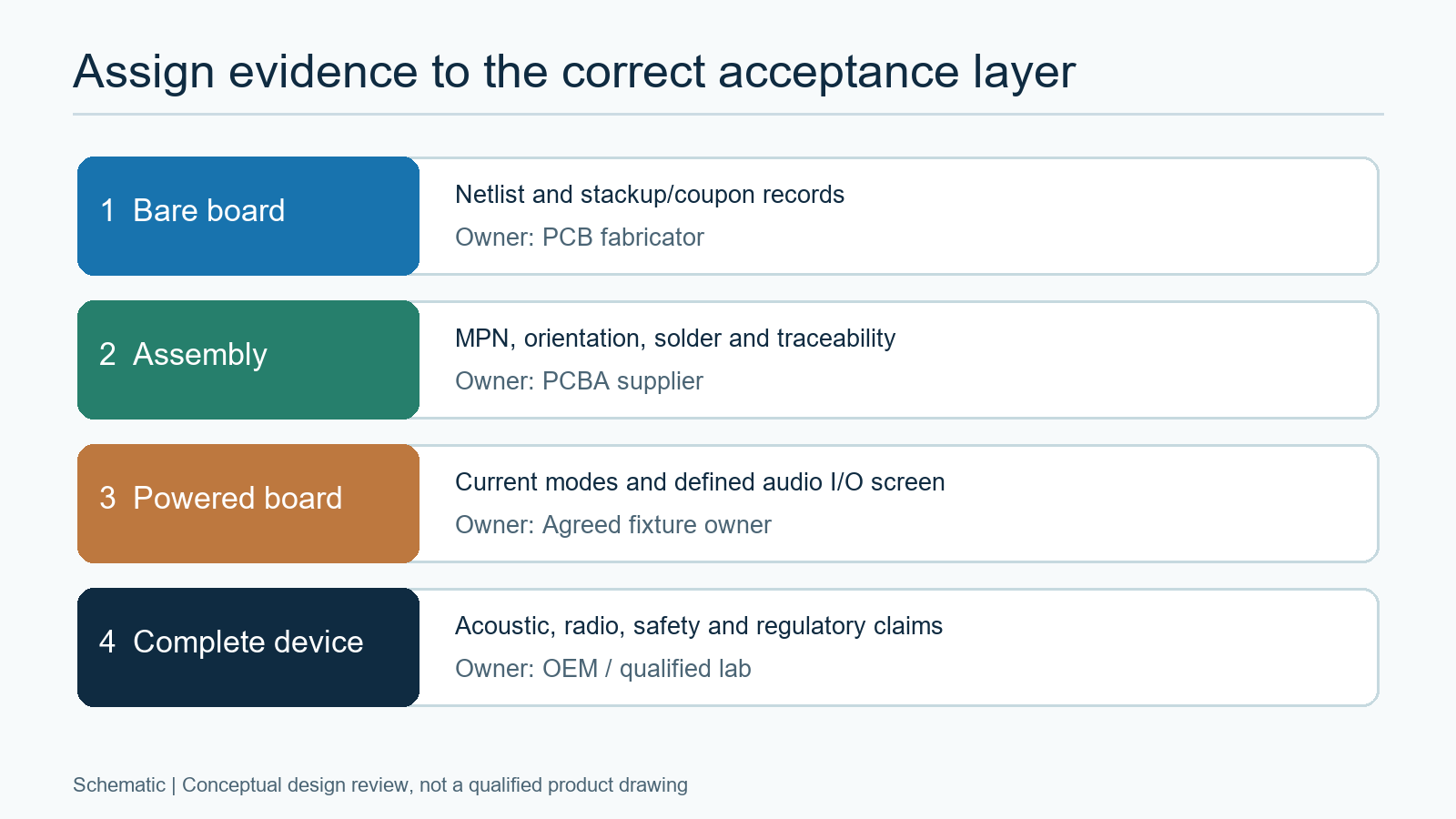
Define a layered acceptance plan so every party knows what its data proves. Bare-board testing can check the released interconnect; assembly inspection can check population, solder and orientation; a powered fixture can measure designated current states, verify programming identity and exercise a specified microphone/receiver path. None of those alone establishes the finished hearing aid’s acoustic response, wireless performance, safety or applicable regulatory status. The enclosure, acoustic coupling, software and user settings all affect the complete-device result.
| Layer | Useful record | Conclusion supported | Still requires separate work |
|---|---|---|---|
| Bare board | Netlist test, approved stackup and relevant coupon results | Released copper interconnect was fabricated and screened | Population, audio, RF and enclosure behavior |
| Populated PCBA | MPN, polarity, solder/hidden-joint inspection and lot traceability | Assembly matches the controlled variant | Firmware state and functional audio path |
| Powered board | Firmware ID, defined current modes and fixture audio I/O result | Specified board behavior under documented fixture conditions | Finished-device acoustic and RF performance |
| Complete device | OEM acoustic, radio, safety and regulatory test plan/results | Product behavior for the approved configuration and market | Automatic coverage of an unreviewed change |
The FDA guidance distinguishing hearing aids from personal sound amplification products is a reminder that the intended-use and device classification questions belong to the product maker and relevant regulators. Board fabrication or assembly records are valuable traceability inputs; they do not turn a supplier into the owner of the medical-device submission or make every populated board clinically acceptable.
For a production audio screen, specify the signal stimulus, coupling arrangement, firmware mode, microphone and receiver variant, measurement unit, ambient conditions and pass/fail limit. If the fixture uses an electrical loopback instead of the physical acoustic path, say so plainly. Correlate board-level measurements with complete-device validation on approved prototypes before using them as release limits. Keep failed-board logs informative enough to separate programming, leakage, microphone, receiver and interconnect faults.
Quote the approved design and test scope, not a generic tiny PCB
An actionable RFQ includes the product variant matrix, 3D enclosure and board model, complete fabrication package, stackup and flex details, approved BOM with alternates, assembly drawings, forecast quantities, programming files, test-fixture interface, acceptance criteria and record-retention requirements. Identify which party supplies the microphones, battery and receiver, and whether components arrive as reels, trays or preassembled modules. State any customer-owned tooling and how revisions will be controlled.
Compare suppliers on the actual process constraints: microvia structure and registration, fine-pitch assembly plan, flex handling, acoustic-port protection, inspection of hidden joints, traceability, and ability to run the specified current/audio screen. Ask for a proposal that separates base fabrication/assembly from optional programming, fixture development and specialized test. This makes cost comparisons meaningful without assuming a supplier can validate a complete hearing aid from PCB data alone.
When the release package and acceptance owners are settled, send the controlled PCB, BOM, assembly and test package for a project quote. The useful outcome is a documented manufacturing scope and a list of unresolved engineering decisions, while product-level acoustic and regulatory approval remains with the OEM.
Latest Blog


Contact Info
Phone: +86-755-82882936
Email: [email protected]
WhatsApp: +86-13570802455
Wechat: +86-13570802455
Address: 2nd floor,D Bldg.,Electric Link Technology Bldg.,Gongming,Guangming New Dist.,518106 Shenzhen, China