
ESP Controller PCB: Choose Rigid-Flex and Define the Safety Boundary

Table of Conent
Table of Conent
An electric submersible pump (ESP) controller PCB does not automatically need a rigid-flex stackup or an intrinsically safe design. First identify where the controller is installed, which circuits carry motor power, and which conductors connect to field sensors or other potentially exposed equipment. Choose rigid-flex only when the mechanical envelope, assembly sequence, or service motion makes a rigid board and harness a poorer documented choice. Determine whether intrinsic-safety requirements apply to a specific circuit and system interface with the product owner and the responsible protection assessor; the label “ESP controller” alone cannot settle that question. Before requesting PCB fabrication and assembly, release a circuit-boundary drawing, the board’s mechanical use conditions, the applicable standards and editions, and an agreed inspection and test plan. This keeps a convenient interconnect choice from being mistaken for a protection approval and helps suppliers quote the same build.
Map the ESP system before specifying the board
The surface controller, the motor power path, and the sensor interface have different functions; a single “pump PCB” label hides those boundaries. SLB’s ESP overview describes an electric motor and pump downhole, with surface controls and variable-speed drives managing the power delivered to the motor. A project may also collect downhole measurements through field wiring. The OEM should therefore name the particular PCB being procured: a drive-related power board, a low-voltage control or monitoring assembly, an interface board, or a combination with defined isolation and interconnection.
On the system drawing, mark the installation location of each enclosure, connector and external conductor. Record the highest relevant operating and fault conditions for each circuit as design inputs, without assuming that every board in the surface cabinet has the same protection classification. Identify which connections cross into a location requiring hazardous-area evaluation. A drive’s motor path and a measurement interface should not be collapsed into one undifferentiated “intrinsically safe PCB” requirement. The related telemetry PCBA handoff guide discusses why the protection file, circuit limits and manufacturing evidence need a named owner.
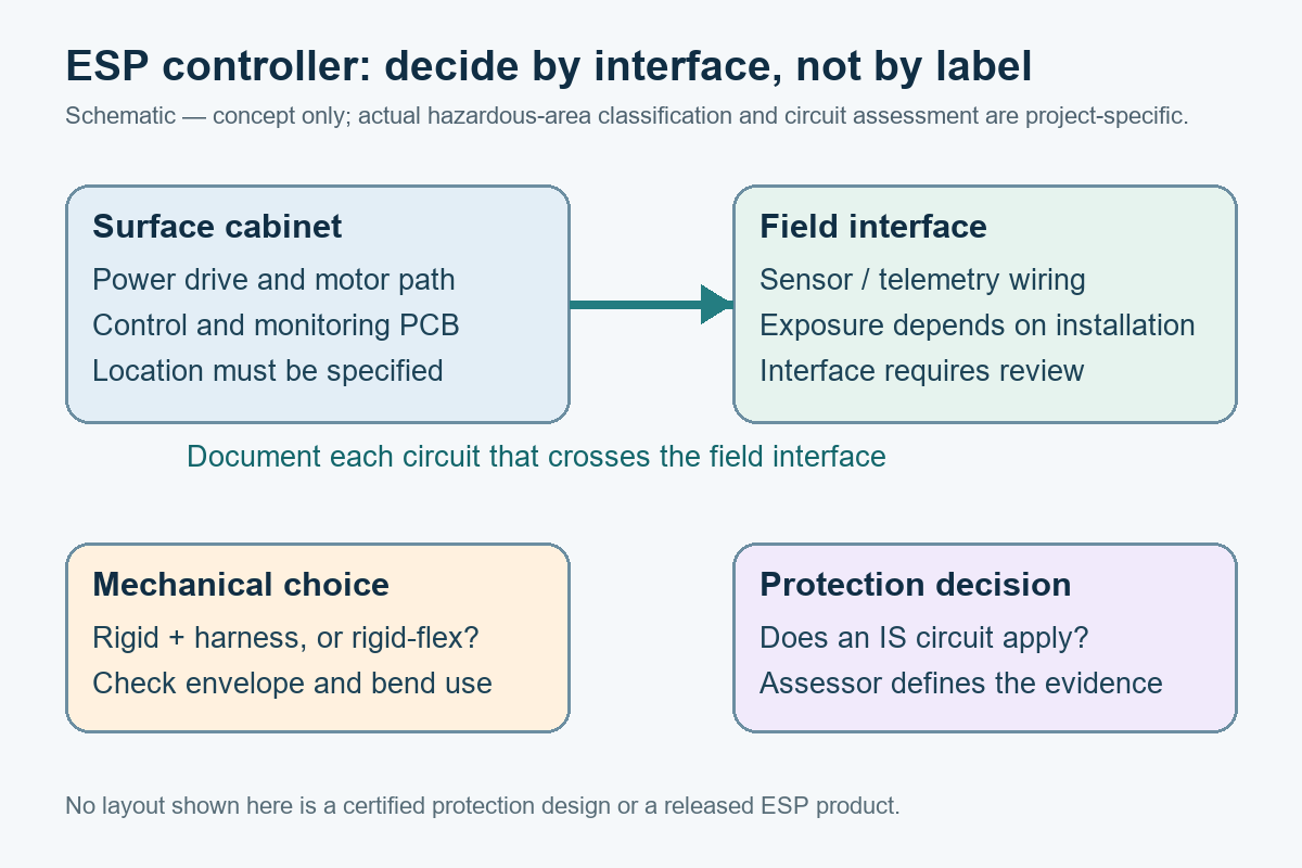
The output of this step is a boundary drawing and circuit list, not a claim that a particular PCB is safe in a hazardous location. The system owner supplies the installation classification and intended protection method; a qualified assessor determines the applicable evidence and acceptance route.
Choose rigid-flex only when its mechanical benefit survives the build review
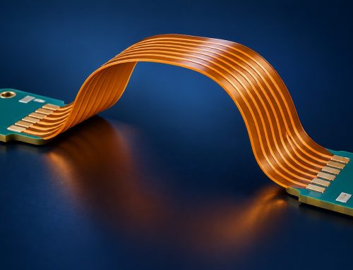
Rigid-flex is justified by a defined interconnect problem, not by the fact that a controller serves a downhole pump. It can route a connection through a tight enclosure or remove a connector between rigid sections, but it also changes the board fabrication, assembly support, inspection access and rework plan. A rigid board plus cable or harness may be easier to assemble and replace when space and connector reliability are acceptable. The procurement comparison should use the actual envelope and service model rather than a generic reliability claim.
| Decision input | Rigid board plus harness | Rigid-flex board | Evidence to request |
|---|---|---|---|
| Enclosure fit and routing | Useful when a serviceable connector and cable route fit without strain. | Consider when a controlled fold or tight routing path removes an otherwise problematic interconnect. | Enclosure CAD, connector keepouts, installation sequence and routing drawing. |
| Movement in service | Specify cable support and connector retention for the actual vibration and maintenance conditions. | Specify whether the flexible region is static after assembly or cycles in service; qualification depends on that use. | Bend location, motion envelope, service-cycle requirement and strain-relief plan. |
| Manufacturing and replacement | Board and harness can be built and replaced separately, subject to connector and harness controls. | One integrated fabricated board requires agreement on flex materials, transition, handling and assembly fixturing. | Stackup, panel drawing, approved material substitutions, inspection and repair disposition. |
| Supplier and cost decision | Compare harness assembly, connector sourcing, mating inspection and installation labor. | Compare specialized board fabrication, yield evidence, assembly support and replacement scope. | Equivalent lot quantity and test scope for both quote options. |
IPC’s design standards overview places IPC-2223 alongside the generic and rigid-board design documents for flexible and rigid-flex applications. The IPC-6013 flex and rigid-flex guide distinguishes a board performance specification from a finished product’s operating qualification. Neither document makes a particular ESP installation mechanically suitable on its own. The released drawing must establish the applicable edition, stackup, bend location and use conditions for the fabricator to review. A rigid-flex PCB service description can help frame a fabrication inquiry, but the submitted geometry and acceptance criteria still control the decision.
If the enclosure is still changing, the first useful supplier conversation is about the feasible transition and assembly support, not a promised cycle life. For a concrete review, share the enclosure drawing and flex-use assumptions for review, together with a preliminary stackup, quantities and the proposed connector alternative. The response can compare fabrication and assembly assumptions before a rigid-flex layout is frozen.
Apply intrinsic-safety requirements to the right circuit and system
Intrinsic safety is an assessed protection method for applicable electrical circuits, not a decorative property of the whole controller PCB. The official IEC 60079-11:2023 scope covers intrinsically safe apparatus and associated apparatus connected to intrinsically safe circuits entering explosive atmospheres. It also recognizes that relevant associated equipment can be outside the hazardous atmosphere. IEC 60079-25:2020 addresses intrinsically safe electrical systems. Which documents and editions govern a project depends on the equipment, jurisdiction, protection concept and assessment plan.
Begin with a circuit-by-circuit interface register. For each field connection, identify the external equipment, location, conductor path, available energy under normal and specified fault conditions, isolation or limiting elements, and the responsible assessor. If a field measurement interface is intended to be intrinsically safe, its protection boundary, approved components, layout controls and production checks must be defined by the project evidence. The motor-drive power path should be analyzed under its own applicable electrical and installation requirements; do not presume that calling one sensor interface “IS” qualifies a power board, cabinet or complete ESP installation.
A rigid-flex bend does not create intrinsic safety, and a rigid-only board does not prevent it. Conversely, a protection assessment does not prove that the flex region survives assembly or service. Keep the mechanical design file and the protection file linked through the same revision-controlled board definition, while allowing each decision to retain its own test and approval owner. No numeric spacing, entity parameter or bend-radius value in this article substitutes for the licensed standard and project-specific assessment.
Release a flex stackup and inspection plan that match the use case
A rigid-flex RFQ needs a physical build definition, not merely a Gerber package marked “flex.” Identify the rigid and flexible zones, layer count in each, material and coverlay selections, copper and finish requirements, transition geometry, component and connector keepouts, and the final installed bend shape. Specify whether the bend is made once during assembly or repeated during maintenance or operation. These inputs affect fabrication feasibility, assembly fixture design and what evidence a supplier can provide. Refer to the current applicable IPC-2223 design and IPC-6013 performance editions in the procurement documents rather than relying on an undated generic claim. IPC’s standards-status listing identifies IPC-2223F and IPC-6013F as 2026 releases; confirm the edition adopted by the project before quoting or accepting a board.
Agree on how the flex area will be supported and protected through solder paste printing, placement, reflow, depaneling, final assembly and shipment. Keep the intended bend zone clear of unintended component placement and define how the transition will be visually inspected under the applicable drawing and acceptance plan. Do not invent a universal bend radius or claim that a single factory photograph proves compliance. The separate IPC-2221C release guide explains why generic board rules, sectional requirements and a fabricator’s actual process limits should be reconciled before design release.
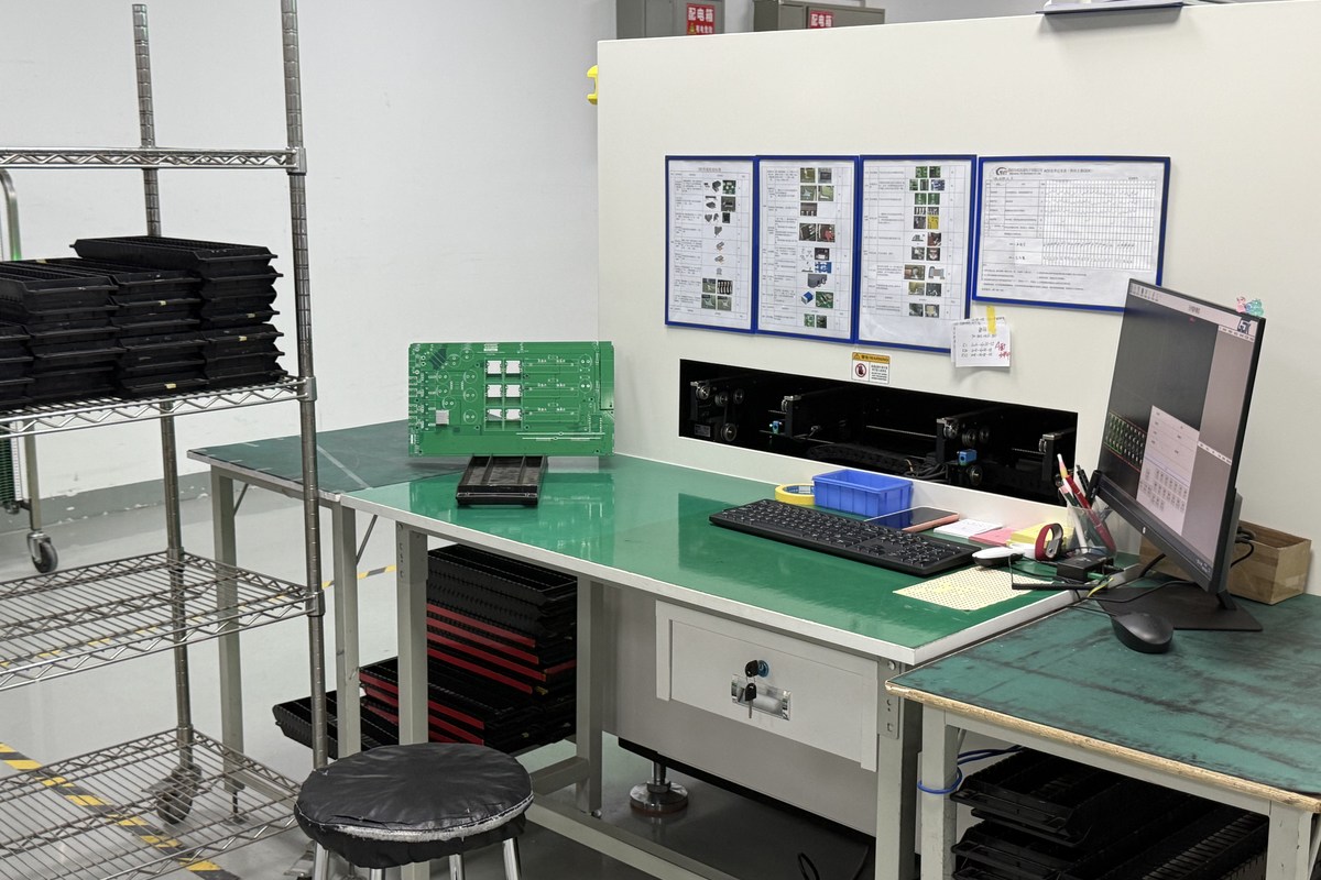
For a rigid-plus-harness alternative, document connector mating, retention, cable routing and accessibility in the same level of detail. A quote comparison is meaningful only when both variants include the same quantities, assembly boundary, testing and field-replacement assumptions. Omitting harness installation from one price while including rigid-flex fabrication in the other is not an engineering comparison.
Give fabrication, assembly and assessment teams one controlled package
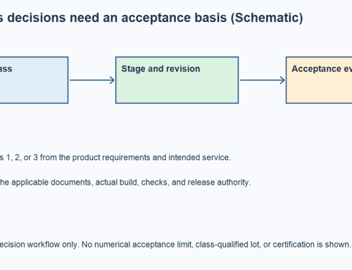
One revision-controlled package should connect the ESP system boundary to the board build and the test evidence. The system owner should state which entity approves each requirement; the PCB supplier should not be asked to infer hazardous-area classification from the project name. The table below is a handoff worksheet, not an exhaustive certification checklist.
| Decision owner | Released input | Evidence or question to resolve |
|---|---|---|
| ESP system / safety owner | Installation location, circuit-boundary drawing, field connections, intended protection route and applicable editions. | Which circuits require IEC 60079-11 or system-level IEC 60079-25 assessment, and who signs the protection file? |
| Mechanical / electronics design | Enclosure model, fixed versus cycling bend use, stackup, keepouts and connector alternative. | Does rigid-flex solve a real mechanical or reliability constraint better than rigid plus harness? |
| PCB fabricator | Controlled fabrication data, layer/zone drawing, materials, finish and agreed inspection criteria. | Can the proposed transition, tolerance and material set be made under the cited board specification? |
| Assembler / sourcing owner | Revision-controlled BOM, approved alternates, placement files, assembly drawings, build quantity and test scope. | What fixturing, component availability and functional checks are included in the assembly quote? |
For the first fabrication review, provide board data in the agreed Gerber, ODB++ or IPC-2581 format, a stackup and zone drawing, and the critical mechanical assumptions. For an assembly quotation, add the BOM with approved alternates, pick-and-place data, assembly drawings, build quantities, programming and test requirements. If a hazardous-area protection claim is intended, include the approved circuit limits, design controls and assessment responsibility; a contract assembler’s general inspection record is not a substitute for that file. The full-turnkey PCB assembly scope is relevant when fabrication, component sourcing and assembly need to be evaluated as one project, subject to the actual submitted files and service agreement.
Once the boundary, board construction and test scope are controlled, send the controlled board and assembly package with the quantities and any required protection-file interfaces. This gives the manufacturing team a basis to review board feasibility, component supply, assembly support and the project-specific test scope together, while the OEM and its assessor retain design and compliance approval.
The release decision is conditional, not a label
For an ESP controller PCB, first separate surface drive power from control and field-interface circuits, then test the mechanical case for rigid-flex against a rigid board and harness. Apply intrinsic-safety review only where the actual circuit, installation and protection strategy require it. A controlled drawing set, standards editions, BOM, assembly files and named approval owners make those choices visible to fabricators, assemblers and assessors. Neither a flexible interconnect nor a general PCB inspection record certifies the complete ESP system.
Latest Blog



Contact Info
Phone: +86-755-82882936
Email: [email protected]
WhatsApp: +86-13570802455
Wechat: +86-13570802455
Address: 2nd floor,D Bldg.,Electric Link Technology Bldg.,Gongming,Guangming New Dist.,518106 Shenzhen, China