
Dot Peen Controller Box Builds: Align PCB, Enclosure and Acceptance Tests

Table of Conent
Table of Conent
A dot peen controller is ready for box build only when the PCB assembly, enclosure, wiring, power components, marking-head interface, firmware, labels, and acceptance tests describe one controlled product configuration. A functional PCBA is not enough. Mechanical fit, grounding, cable routing, connector keying, strain relief, thermal behavior, safety interfaces, and system-level test all become part of the delivered assembly.
The most reliable handoff defines interfaces before production: released fabrication and assembly data, an enclosure drawing, wiring and harness documentation, a mechanical bill of materials, torque and workmanship requirements, firmware and parameter files, inspection points, and measurable acceptance limits. Build the first units as controlled integration articles, close fit and test findings, then release repeatable work instructions and a traceable final test record.
Define the box-build boundary and ownership
A box build is the integration of electronic, electrical, and mechanical items into a finished enclosure or subassembly. For a dot peen controller, the scope may include the populated PCB, power supply, terminal blocks, relays, HMI, switches, indicators, fans, filters, cable glands, internal harnesses, protective earth, external cables, marking-head interface, firmware, labels, packaging, and final test. The purchase order should state exactly which items are supplied, assembled, programmed, tested, and packed by each party.
Create an interface-control list with an owner and acceptance method for every connection. Identify supply voltage and protective devices, grounding points, connector families, pinouts, cable lengths, shield termination, I/O voltage levels, communication protocols, encoder or trigger signals, emergency-stop and guard circuits, pneumatic or solenoid interfaces, and the marking head’s current and timing requirements. Open assumptions should be visible rather than left to line-side interpretation.
The same revision-control principles in the PCB design-transfer package apply to enclosure integration. The Gerbers, BOM, placement data, assembly drawing, wiring diagram, firmware, enclosure drawing, and test specification must all reference compatible releases.
Release a complete manufacturing package
The box-build package should contain documents that can be built and inspected without relying on tribal knowledge. At minimum, provide the PCB manufacturing files, PCBA BOM, pick-and-place data, assembly drawings, mechanical BOM, 2D enclosure drawings or controlled 3D data, wiring diagram, harness drawings, connector tables, label artwork, firmware binaries, programming instructions, test specification, and packaging requirements.
Mechanical drawings should define critical dimensions, tolerances, material and finish, hole and cutout locations, fasteners, inserts, gasket interfaces, mounting surfaces, and keep-out zones. Harness documentation should specify wire type and gauge, color where controlled, cut length, terminal and contact part numbers, crimp tooling or process requirements, splice rules, shielding, sleeving, labels, routing, bend limits, tie-down points, and continuity map.
Record configuration dependencies explicitly. A controller board revision may require a particular enclosure cutout, display cable, power-supply rating, marking-head firmware, or fixture adapter. The EVT build handoff checklist provides a useful model for assigning owners to files, material decisions, programming, first articles, and test readiness before the build begins.
Design the enclosure around electrical and service needs
Enclosure design must support safe operation, predictable thermal behavior, reliable wiring, and practical service. Position the controller PCB, power supply, terminal blocks, disconnects, filters, and high-energy circuits so that required clearances, cable bend space, airflow, access, and separation can be maintained. Do not assume a component’s catalog outline includes connector removal space or tool access.
Define protective-earth bonding, chassis connections, cable-shield termination, and signal-reference strategy. Paint, anodizing, gaskets, thread-locking compounds, and removable panels can change electrical continuity. Bonding surfaces and hardware should be deliberate, inspectable, and compatible with the product’s safety and EMC design. For machine electrical equipment, IEC 60204-1 is a relevant system-level reference in applicable projects, but contractual requirements depend on the target market, machine architecture, and governing standards.
Thermal review should include power dissipation, ambient conditions, enclosure material, ventilation, heat paths, cable crowding, and duty cycle. A bench test with the door open does not represent a sealed enclosure. Instrument early units under representative marking cycles, with the intended power supply and loads, and define temperature limits from the actual component and product requirements.
Control harness fabrication and installation
Harnesses are engineered assemblies, not loose accessories. Terminal selection, strip length, crimp geometry, pull strength, soldering when allowed, insulation support, connector assembly, strain relief, routing, and labeling all affect reliability. IPC identifies IPC/WHMA-A-620E as the current revision of its requirements and acceptance standard for cable and wire harness assemblies; the purchase order still needs to state the applicable revision, class, addenda, and customer-specific criteria.
Inside the enclosure, route power, motor, solenoid, communications, encoder, and low-level sensor wiring according to the electrical design. Preserve bend radius, keep wires away from sharp edges and hot surfaces, protect pass-throughs, avoid loading soldered joints, and provide service loops only where they improve maintenance without creating interference or abrasion. Connector keying and labels should make an incorrect field connection difficult.
If the released package is ready for integration review, share the Gerbers, BOM, placement data, enclosure drawings, harness files, build quantity, and acceptance-test requirements for one coordinated box-build assessment. The review should expose missing interfaces, sourcing assumptions, fixture needs, and responsibility gaps before material is committed.
Use first articles to close mechanical and electrical risks
The first box-build units should prove both fit and process. Inspect board mounting, standoff height, connector alignment, cable-gland engagement, door clearance, harness routing, label placement, grounding, access, fastener engagement, and marking-head connections. Record discrepancies against the controlled design, not as informal line adjustments.
Define torque requirements only where engineering has selected the joint, hardware, material, lubrication condition, and locking method. A generic torque value copied across all fasteners can damage plastic bosses, distort PCBs, compromise terminals, or loosen in service. The work instruction should identify the tool, setting, sequence, witness marking if required, and verification method.
Changes found during integration need a formal review. A moved connector can affect cable length; a different power supply can alter heat and protection; a firmware update can change I/O behavior; a new enclosure finish can affect bonding. Use the DVT change-impact and regression-test method to map each change to affected requirements, documents, samples, and retesting before release.
Build acceptance testing in layers
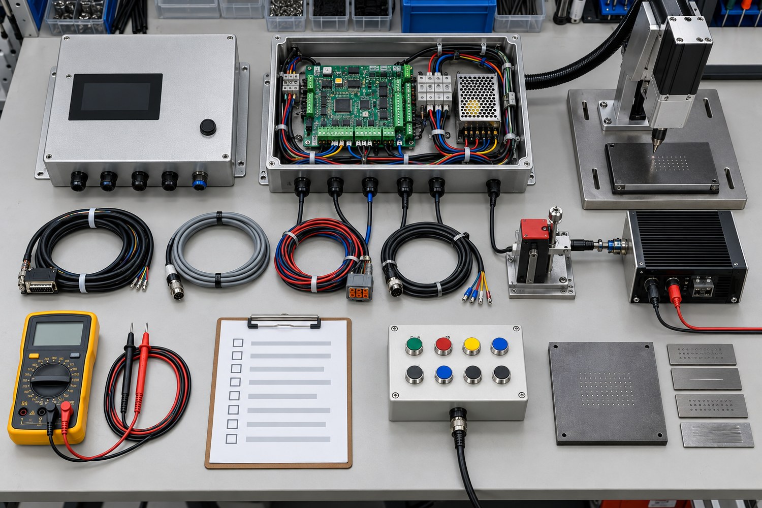
A layered test sequence contains faults and reduces diagnostic time. Begin with configuration and workmanship checks before applying power. Verify part numbers, revision labels, connector positions, fasteners, grounding, harness routing, and obvious damage. Then perform the electrical checks appropriate to the design, such as continuity, isolation, protective-earth bonding, polarity, short-circuit screening, and connector pin mapping.
Controlled power-up should use the intended voltage and suitable current limiting or protection. Record standby current, power rails, indicator state, firmware identity, and fault behavior. Next, test inputs and outputs with representative loads or validated simulators. For a dot peen system, this may include trigger input, marking-head drive, motion or solenoid outputs, encoder feedback, communications, HMI, interlocks, alarms, and parameter retention.
| Test layer | Purpose | Example evidence |
|---|---|---|
| Configuration inspection | Confirm the released hardware and documentation match | Serial number, revision, firmware, BOM and label record |
| Mechanical inspection | Verify fit, mounting, cable entry, routing and access | Checklist, critical dimensions, torque record where required |
| Electrical safety and wiring | Detect incorrect connections and bonding problems before operation | Continuity, polarity, isolation and protective-earth results as applicable |
| Functional test | Verify controller behavior with realistic interfaces | I/O responses, communications, faults, marking cycle and stored results |
| Final inspection | Confirm closure, labeling, accessories and packaging | Pass record tied to unit identity and test revision |
The final marking test should state the representative material or fixture, operating mode, required pattern, readable result, fault response, and acceptance limits. A visually plausible mark is not a complete electrical test, while a simulated output does not prove the mechanical marking interface. Use both where the product risk requires them.
Specify workmanship standards without leaving gaps
Different standards cover different parts of the assembly. IPC-A-610 and J-STD-001 address electronic assembly workmanship; IPC/WHMA-A-620 addresses cable and harness requirements; IPC-A-630 covers manufacture, inspection, and testing of electronic enclosures according to IPC’s document revision table. None of these automatically defines the product’s wiring diagram, torque, firmware, safety functions, functional behavior, or marking performance.
The contract should identify the selected revision, class, addenda, exceptions, sampling, and product-specific acceptance criteria. If the finished unit is part of an industrial control panel or machine, regulatory evaluation can extend beyond PCB and harness workmanship. UL provides current UL 508A component guidance for industrial control panels, but applicability and certification must be determined for the actual product and market.
A one-stop PCB assembly workflow is most useful when fabrication, component sourcing, PCBA, harnesses, enclosure integration, programming, and test are governed by the same released configuration. That does not remove the customer’s design authority; it reduces fragmented handoffs and makes open assumptions easier to resolve.
Release production with traceability and change control
Every finished controller should be traceable to the information needed for containment and service. The appropriate record may include serial number, work order, PCBA lot, enclosure and harness revisions, firmware and parameter versions, key material lots, test fixture and software revisions, test result, operator or station, and disposition. The required depth depends on product and contractual risk.
Define how deviations, substitutions, rework, firmware updates, drawing changes, and test-limit revisions are approved. Quarantine uncertain configurations and reconcile work in process before a new revision becomes effective. Preserve a golden unit only as a comparison aid; the released documents and measurable limits remain the authority.
When the package and test limits are controlled, provide the complete PCB, mechanical, harness, firmware, quantity, compliance, and final-test package for production planning and quotation. The resulting review should confirm scope, open technical items, material responsibility, validation activities, traceability, and deliverables before the build is released.
Conclusion
A dependable dot peen controller box build begins with interface control and ends with a unit-specific acceptance record. Align the PCBA, enclosure, harnesses, grounding, thermal design, firmware, labels, and marking-head behavior under one revision. Use first articles to close integration findings, layered tests to contain faults, and explicit standards plus product-specific limits to define acceptance.
The result is a manufacturable assembly rather than a collection of parts: the enclosure fits, the wiring is controlled, the controller behaves as intended, and production has enough evidence to repeat and support the configuration.
Latest Blog
Contact Info
Phone: +86-755-82882936
Email: [email protected]
WhatsApp: +86-13570802455
Wechat: +86-13570802455
Address: 2nd floor,D Bldg.,Electric Link Technology Bldg.,Gongming,Guangming New Dist.,518106 Shenzhen, China