
Scaling Inkjet Printer Control Boards from Prototype to Production
Table of Conent
Table of Conent
Scaling an inkjet printer control board from prototype to production requires more than ordering a larger batch. The design, BOM, fabrication data, assembly process, firmware, fixtures, acceptance criteria, and supplier responsibilities must become controlled and repeatable. A prototype that works after bench rework is evidence of function; it is not yet evidence that hundreds or thousands of boards can be built, tested, traced, and serviced consistently.
The safest ramp uses gated stages: freeze the intended revision, close DFM and sourcing risks, run a controlled pilot build, validate the process and functional test, then increase volume only after the evidence supports it. For an inkjet controller, particular attention belongs on printhead drive, waveform timing, power integrity, motion control, sensors, communications, fluid-system interlocks, firmware configuration, and representative load testing.
Define what “production ready” means
Production readiness is an agreed set of exit criteria. The design should have a released revision, resolved critical engineering questions, approved materials and alternates, stable firmware, manufacturable land patterns, accessible test points, and measurable acceptance limits. The supplier should know which changes need written approval and which process adjustments remain within its normal manufacturing control.
Create a readiness checklist with owners and evidence. Include schematic and layout review, DFM and DFA closure, component lifecycle review, fabrication stackup approval, assembly drawing, programming package, functional-test specification, fixture status, packaging, traceability, and first-article approval. Unresolved items should be visible risks, not hidden in meeting notes.
The controlled design-transfer practices in the PCB manufacturing handoff guide apply directly to an inkjet controller. Every fabrication, assembly, firmware, and test artifact must describe the same revision and product configuration.
Close DFM and assembly risks before increasing quantity
A production DFM review asks whether the intended board can be fabricated and assembled repeatedly within the released tolerances. It should reconcile stackup, copper, drills, solder mask, surface finish, panelization, controlled impedance, component geometry, stencil strategy, polarity, thermal mass, depaneling, and test access. A structured PCB DFM report should track each issue to disposition and approval.
Inkjet control electronics may place sensitive logic near pulsed high-current loads. Review return-current paths, plane continuity, connector pin assignments, protection devices, thermal spreading, high-current vias, and separation between noisy drive circuits and low-level sensing. Confirm that the production stackup and copper construction match the prototype assumptions rather than accepting an unreviewed quotation stackup.
Assembly risk depends on the actual packages and process. Fine-pitch ICs, bottom-terminated components, large thermal pads, mixed thermal mass, connectors, and through-hole power parts may need specific stencil, reflow, X-ray, selective-solder, or fixture planning. Prototype hand soldering can mask pad-design or access problems that become costly in an automated line.
Stabilize the BOM and sourcing rules
A scalable BOM identifies exact manufacturer part numbers, approved alternates, do-not-substitute items, lifecycle status, packaging, moisture sensitivity, programming state, and customer-supplied material. Separate functionally critical parts from ordinary passives. Inkjet-specific risks may include printhead drivers, FPGAs or processors, precision references, isolation devices, power switches, high-current connectors, and long-lead interface modules.
Approve alternates through engineering evidence, not distributor descriptions. Compare electrical limits, tolerances, temperature behavior, package dimensions, pinout, startup state, timing, firmware dependencies, safety or regulatory status, and assembly process needs. The BOM alternate approval workflow provides a practical release-control framework.
Define how shortages, minimum order quantities, excess material, date codes, and noncancelable inventory are handled. If the project is ready for a pilot quotation, share the released fabrication data, BOM with sourcing rules, placement files, pilot quantity, target ramp, and test requirements for one coordinated manufacturing review.
Use the pilot build to validate the process
A pilot build should answer specific production questions. It is large enough to exercise normal tooling, material handling, machine programming, inspection, programming, and functional test, but small enough to contain risk. The appropriate quantity depends on product complexity, supplier process, fixture readiness, and the evidence needed; there is no universal pilot-lot number.
Capture first-article data before releasing the balance of the pilot lot. Confirm component identity and orientation, solder paste deposition, placement, reflow results, through-hole operations, mechanical fit, programming, and basic power behavior. Use AOI, X-ray, visual inspection, measurements, and functional test according to package and product risks.
IPC J-STD-001J addresses soldering processes and materials, while IPC-A-610J addresses post-assembly acceptance. Contractual use still requires the applicable class, revision, and any customer-specific criteria. Neither standard substitutes for product-specific functional tests or engineering limits.
Build a production test that finds relevant failures
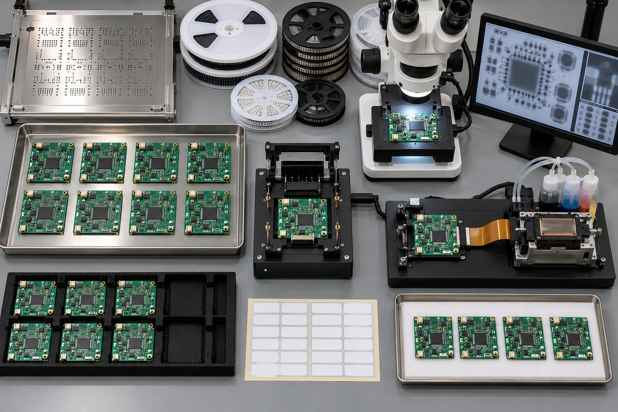
Production test should detect manufacturing defects and configuration errors within a practical cycle time. Start from the product failure modes: opens, shorts, wrong or reversed parts, solder defects, programming failures, power-rail faults, communication errors, sensor-interface faults, driver-channel faults, and incorrect configuration data.
For an inkjet controller, define representative loads and safe substitutes for the printhead, motors, pumps, valves, heaters, sensors, and interlocks. Specify rail sequencing, standby and operating current, communication commands, channel response, timing checks, temperature feedback, fault injection, watchdog recovery, firmware identity, and stored configuration. The fixture should protect both the board and connected loads from an incorrectly assembled unit.
Separate test coverage from test method. AOI verifies visible assembly features; X-ray can evaluate obscured joints; in-circuit or flying-probe testing checks selected electrical nodes; functional test checks behavior. No single method proves all requirements. Record limits, equipment, calibration needs, fixture revision, software revision, result format, and disposition of failures.
Control process changes during the ramp
A production ramp often reveals improvements, but every change needs classification. Supplier process tuning within approved limits is different from a design change, component substitution, stackup change, firmware update, or test-limit revision. Define who can approve each category and how affected work in process is identified.
Track defects by type and process stage, but do not confuse a low observed defect count with complete process capability. Early lots may not represent later material, operators, equipment, or demand mix. Use stable definitions, consistent inspection, and enough context to interpret trends. When a corrective action changes tooling or process parameters, verify the result against controlled acceptance evidence.
IPC-1782 describes manufacturing and supply-chain traceability based on risk agreed between user and supplier. For the ramp, decide which material lots, date codes, process records, programming data, inspection results, rework events, fixture revisions, and functional-test results must connect to each lot or serial number.
Plan capacity without sacrificing configuration control
Volume planning should translate demand into material, tooling, machine, fixture, labor, inspection, test, and packaging requirements. Review long-lead parts, panel utilization, stencil life, feeder availability, programming throughput, functional-test cycle time, fixture count, maintenance spares, and retest capacity. A nominal SMT line rate is not the same as shipped, accepted assemblies per week.
Use staged releases when demand is uncertain. A smaller controlled lot can protect against an impending revision, unproven alternate, or incomplete field feedback. At the same time, late purchasing decisions may increase component risk. Balance these constraints with forecast visibility, approved alternates, and clearly owned inventory.
Preserve approved pilot samples and production golden units under configuration control. Record their PCB, BOM, firmware, calibration, and fixture revisions, and define when they may be replaced. Field-return data should feed the same change process: confirm the failure mode, affected population, containment action, and verification plan before changing a component, layout, process, or test limit. This prevents an urgent correction from creating an untraceable second configuration.
Review the ramp gate again whenever demand, supplier, material, firmware, or test coverage changes materially.
Compare suppliers on the same scope, including fabrication, parts, NRE, tooling, programming, inspection, functional test, failure analysis, packaging, freight, and delivered quantity. The guide to comparing PCB quotes by total delivered cost helps expose assumptions that a unit price alone misses.
Production-ramp release checklist
- One authoritative PCB, BOM, firmware, mechanical, and test revision is released.
- Critical DFM and DFA findings are closed with documented dispositions.
- Stackup, materials, surface finish, panelization, and fabrication evidence are approved.
- BOM sources, alternates, consigned items, shortages, and excess ownership are defined.
- Assembly drawings, placement data, programming files, and population variants agree.
- Pilot-build objectives, first-article gates, inspection coverage, and acceptance criteria are set.
- Functional-test loads, stimuli, limits, fixture revision, software, and result records are controlled.
- Traceability and serialization match product risk and failure-analysis needs.
- Capacity is based on the constrained process, not only nominal placement speed.
- Engineering changes and supplier deviations have written approval paths.
Conclusion
An inkjet printer control board is ready to scale when the product definition and the manufacturing process are both controlled. Close design and sourcing risks, validate a representative pilot build, establish product-specific test coverage, capture traceability, and increase volume through evidence-based gates. This approach reduces the chance that prototype workarounds become production defects.
For the next build stage, provide the controlled Gerber or intelligent data, BOM, placement files, firmware package, pilot findings, forecast quantities, and functional-test definition for production-scope review. OrinewPCB can then evaluate a full turnkey PCB assembly plan covering fabrication, component sourcing, assembly, programming, test, and delivery coordination.
References
Latest Blog

Contact Info
Phone: +86-755-82882936
Email: [email protected]
WhatsApp: +86-13570802455
Wechat: +86-13570802455
Address: 2nd floor,D Bldg.,Electric Link Technology Bldg.,Gongming,Guangming New Dist.,518106 Shenzhen, China