
Label Printer PCB Design Transfer: Prepare a Complete Manufacturing Handoff
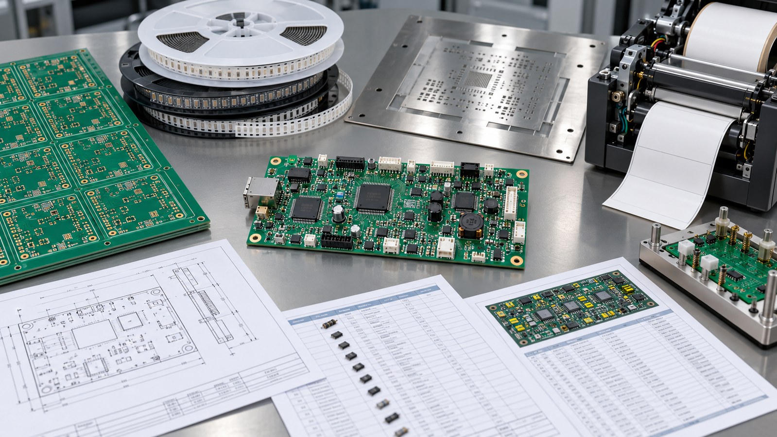
Table of Conent
Table of Conent
A complete label-printer PCB design transfer is a controlled manufacturing release, not a folder of Gerbers. The package should let a PCB fabricator, component buyer, assembler, programmer, inspector, and functional-test engineer build the same revision without guessing. At minimum, it connects fabrication data, stackup and drawing requirements, BOM and approved parts, placement data, assembly documentation, firmware, test limits, change history, and acceptance evidence.
The most important rule is consistency. Every file must describe the same board revision, coordinate system, units, polarity, component population, and product configuration. Intelligent exchange formats can reduce manual interpretation, but no format replaces engineering approval of the released content. For a high-speed label-printer controller, the handoff also needs to preserve printhead power, motor drive, sensor interfaces, communications, thermal management, programming, and test assumptions.
Freeze one authoritative product revision
A manufacturing handoff begins with a named release and a responsible approver. Assign the PCB, BOM, firmware, mechanical interface, test specification, and assembly drawing to one product revision. Record the release date, approved deviations, and any configuration variants. A supplier should never have to decide whether “final,” “final-v2,” or an email attachment is authoritative.
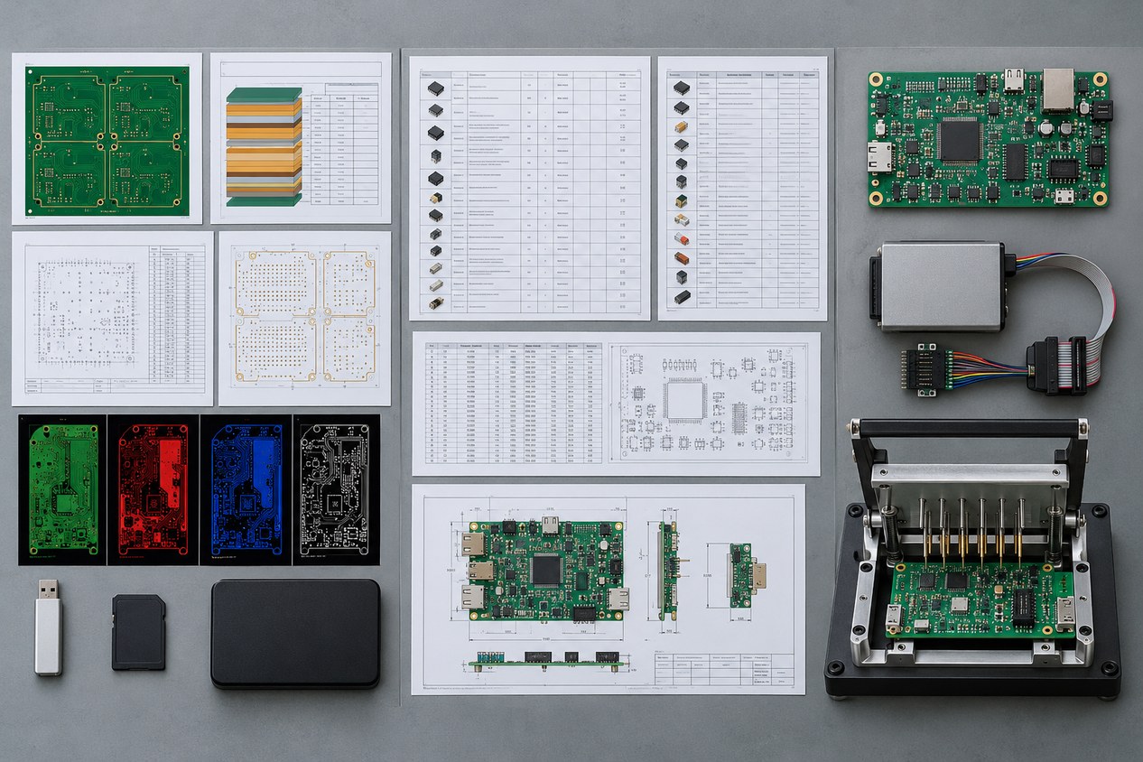
Include a release index that lists each file, its revision, date, purpose, and checksum when your document-control process supports it. The index should identify the native source ownership but send only the manufacturing outputs needed for the build. If multiple label-printer models use the same controller with different options, define those options through controlled population variants rather than informal notes.
Change control continues after release. A fabrication query, component substitution, footprint correction, or test-limit change must be captured as an approved record tied to affected lots. Do not let a supplier’s corrected CAM file or shop-floor note become an undocumented design revision.
Build a fabrication package that can be checked independently
The fabrication package must define copper, holes, outline, stackup, materials, finish, solder mask, legend, tolerances, impedance, special processes, panel constraints, markings, and inspection or test evidence. It should include a netlist or other independent connectivity reference so that bare-board electrical test is not derived only from the same artwork being tested.
IPC-2581 defines an XML-based intelligent format for transferring printed-board and assembly product information for tooling, manufacturing, assembly, and inspection. ODB++ also provides a structured design-through-manufacturing data exchange. If the supply chain uses Gerber, drill files, drawings, and netlists instead, the release index must make their relationships and revisions unambiguous. The chosen format is less important than a supplier’s ability to import, inspect, and compare it reliably.
A fabrication drawing should state requirements that geometry files cannot express safely. That includes applicable specifications and revisions, board type, finished thickness, copper construction, material performance, surface finish, controlled impedance, hole and route tolerances, via treatment, edge features, panel or coupon requirements, serialization, packaging, and required reports. Use the PCB thickness selection guidance to confirm that the released stackup matches connector, stiffness, enclosure, and process needs.
Release assembly data as one coordinated set
The assembly package should include the BOM, centroid or pick-and-place file, assembly drawings, polarity and orientation information, approved population variants, and special process notes. These files must agree on reference designators. Missing or duplicated designators, unplaced parts in the centroid file, and mismatched package names are common causes of quotation holds and first-article errors.
The BOM needs manufacturer part numbers, quantities, descriptions, reference designators, approved alternates, do-not-substitute rules, lifecycle or sourcing notes where relevant, and clear handling of customer-supplied parts. A controlled BOM alternate approval process prevents a commercial substitution from silently changing voltage rating, tolerance, temperature behavior, package geometry, firmware compatibility, or regulatory status.
The assembly drawing should show side, orientation, mechanical relationships, hardware, adhesives, jumpers, depaneling restrictions, conformal coating or staking where required, and any post-assembly operations. A practical PCB assembly drawing checklist helps separate visible build instructions from information that belongs in the BOM, fabrication drawing, or test specification.
Document label-printer-specific interfaces and loads
A label-printer controller often combines logic with pulsed printhead power, stepper or DC motor drive, sensors, cutters, encoders, communications, and user-interface connections. The design transfer should identify connector pinouts, mating parts, cable assumptions, supply range, peak and continuous currents, duty cycle, protection behavior, grounding, shielding, and mechanical keepouts. These details allow the manufacturer to distinguish a manufacturing defect from an incomplete or unrealistic test setup.
Define the printhead interface without exposing proprietary information that is not needed for production. Specify the load model, pulse conditions, timing dependencies, connector limits, temperature or resistance feedback, and safe test substitute. For motor and cutter outputs, describe representative current, acceleration, stall or jam protection, and recovery behavior. Sensor inputs should have test points or fixture access when production validation requires them.
Use a structured PCB DFM report to reconcile the manufacturing data against the drawing, stackup, component geometry, tooling rules, and test access. If the released package is ready, send the fabrication data, BOM, placement file, assembly drawing, build quantity, and label-printer interface requirements for a coordinated DFM and assembly-scope review.
Control firmware, programming, and configuration
Firmware is a manufacturing input when devices must be programmed before, during, or after assembly. Provide the approved binary or image, version identifier, programming method, device security or key-handling requirements, checksum, target reference designator, and acceptance response. Keep source code outside the release unless the contract requires it.
Define whether boards are programmed once, provisioned with serial data, calibrated, or configured for a particular printer model. State how programming success is recorded and how rework or replacement is handled. If a secure element, unique identifier, MAC address, or licensed code is involved, specify who owns the data pool, how it is transferred, and how duplicates are prevented.
A golden unit can support fixture correlation, but it does not replace numeric limits. Identify its hardware and firmware revision, storage conditions, approval record, and permitted use. Production acceptance should rely on controlled measurements and expected states, not only comparison with an undocumented sample.
Define inspection and functional test before quoting
Inspection and test scope determines equipment, fixture, programming, cycle time, reporting, and failure-analysis cost. State the applicable bare-board and assembly workmanship criteria, required AOI or X-ray coverage, first-article evidence, cleanliness or coating checks, and functional-test sequence. Do not request “100% testing” without defining what each board must prove.
For a label-printer controller, a functional test may verify rail sequencing, standby and active current, processor boot, communications, sensor inputs, printhead-driver control, motor outputs, cutter or actuator outputs, fault detection, firmware identity, and recovery from representative faults. The exact list depends on the design. Provide loads, stimuli, timing, limits, measurement accuracy, connector access, fixture responsibility, test-software ownership, result format, and disposition rules.
IPC-D-356B describes a format for bare-board electrical-test information, but bare-board continuity does not prove assembled function. Treat fabrication electrical test, assembly inspection, programming verification, and powered functional test as separate layers of evidence.
Run a pre-release consistency check
Before issuing the package, review it as though the recipient cannot ask the original designer for clarification. The review should confirm:
- The release index names one authoritative revision and every included file.
- Board outline, origin, units, layer order, drill data, and polarity agree across files.
- The netlist and fabrication data describe the intended connectivity.
- BOM, centroid data, and drawings use the same reference designators and population options.
- Manufacturer part numbers, alternates, consigned parts, and substitution rules are explicit.
- Programming images, versions, checksums, configuration data, and ownership are controlled.
- Fixture interfaces, test loads, measurements, limits, and result records are defined.
- Critical label-printer electrical and mechanical interfaces are documented.
- Approved deviations and open questions are visible rather than buried in email.
Normalize the same scope before comparing suppliers. The method for comparing PCB quotes by tooling, test scope, and delivered cost is especially useful when one quotation includes programming and fixtures while another covers only assembly labor.
Archive the exact released package separately from working design folders. Preserve the supplier acknowledgement, approved engineering questions, deviation records, first-article results, and final test reports with the release. This record makes a repeat order, supplier transfer, or failure investigation faster because the organization can reconstruct what was actually authorized and built rather than relying on current CAD files that may already have changed.
Conclusion
A complete label-printer PCB design transfer creates one traceable bridge from engineering intent to fabricated, assembled, programmed, and tested hardware. The package should be internally consistent, manufacturing-ready, and explicit about interfaces, ownership, acceptance, and change control. Intelligent formats can reduce interpretation, but disciplined release governance remains essential.
Freeze the revision, validate fabrication and assembly data, control the BOM and firmware, define label-printer loads and interfaces, and specify measurable test limits. For production planning, provide the controlled release index, Gerber or intelligent data, BOM, placement files, programming package, quantities, and functional-test definition for final engineering and quotation review. OrinewPCB can then evaluate the full turnkey PCB assembly scope, including fabrication, component sourcing, assembly, programming, and test, as one documented manufacturing handoff.
References
Latest Blog

Contact Info
Phone: +86-755-82882936
Email: [email protected]
WhatsApp: +86-13570802455
Wechat: +86-13570802455
Address: 2nd floor,D Bldg.,Electric Link Technology Bldg.,Gongming,Guangming New Dist.,518106 Shenzhen, China