
Aircraft SATCOM Modem Boards: EMS Handoff for RF and Digital Integration
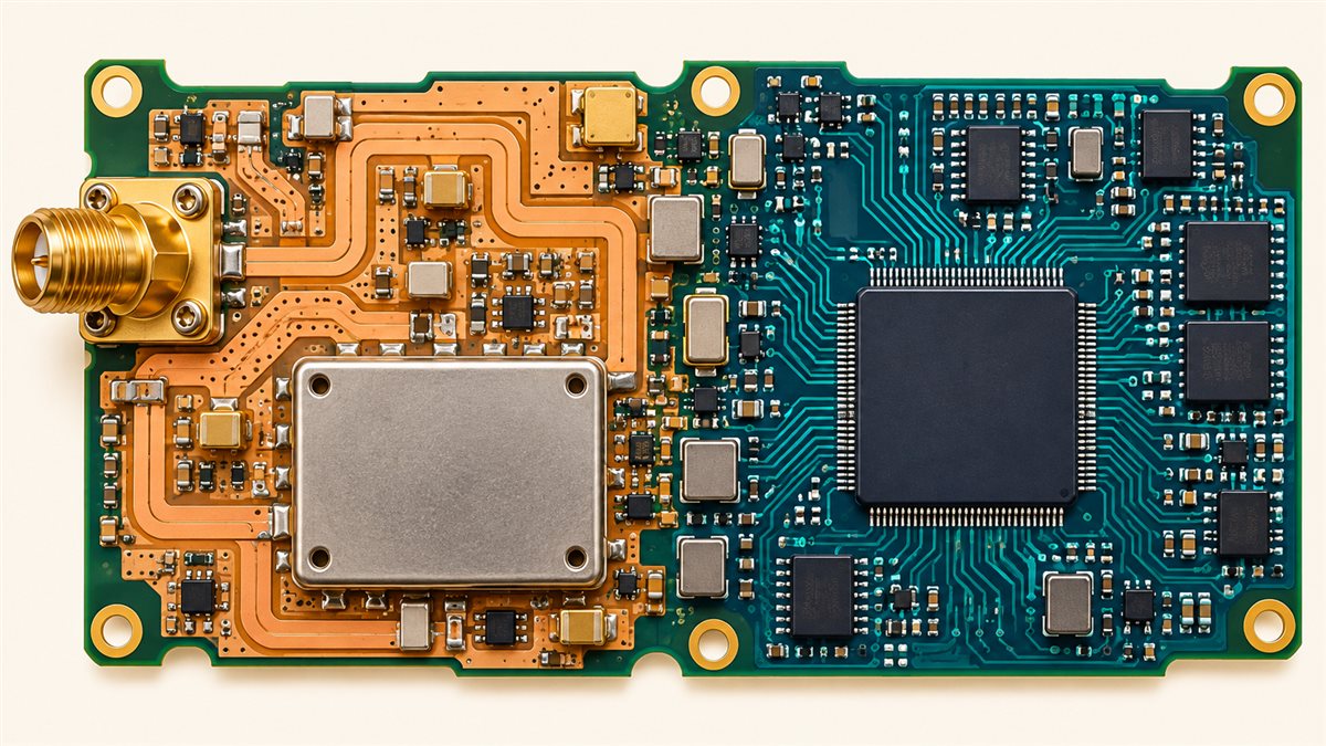
Table of Conent
Table of Conent
An aircraft SATCOM modem board is ready for EMS outsourcing when the OEM has released one configuration that ties the RF path, mixed-signal conversion, digital processing, power, firmware or programmable logic, connectors, and acceptance tests to controlled revisions. A board-level optical inspection alone cannot establish modem performance or aircraft suitability. The purchasing package should therefore define what the supplier must fabricate, assemble, program, inspect, and test, while identifying which RF, environmental, and approval decisions remain with the OEM or design approval holder. Start with an interface and evidence matrix; then price a pilot build against measurable acceptance gates before committing to production.
This checklist applies to a board within a larger SATCOM installation, not to every modem architecture or airworthiness program. Frequency plan, waveform, RF limits, environmental categories, and hardware assurance objectives must come from the approved design and intended installation. The FAA’s AC 20-152A discusses circuit-board-assembly development assurance in its stated scope; it does not make an EMS-built board automatically approved for flight.
Set the RF, digital, and aircraft-system boundaries first
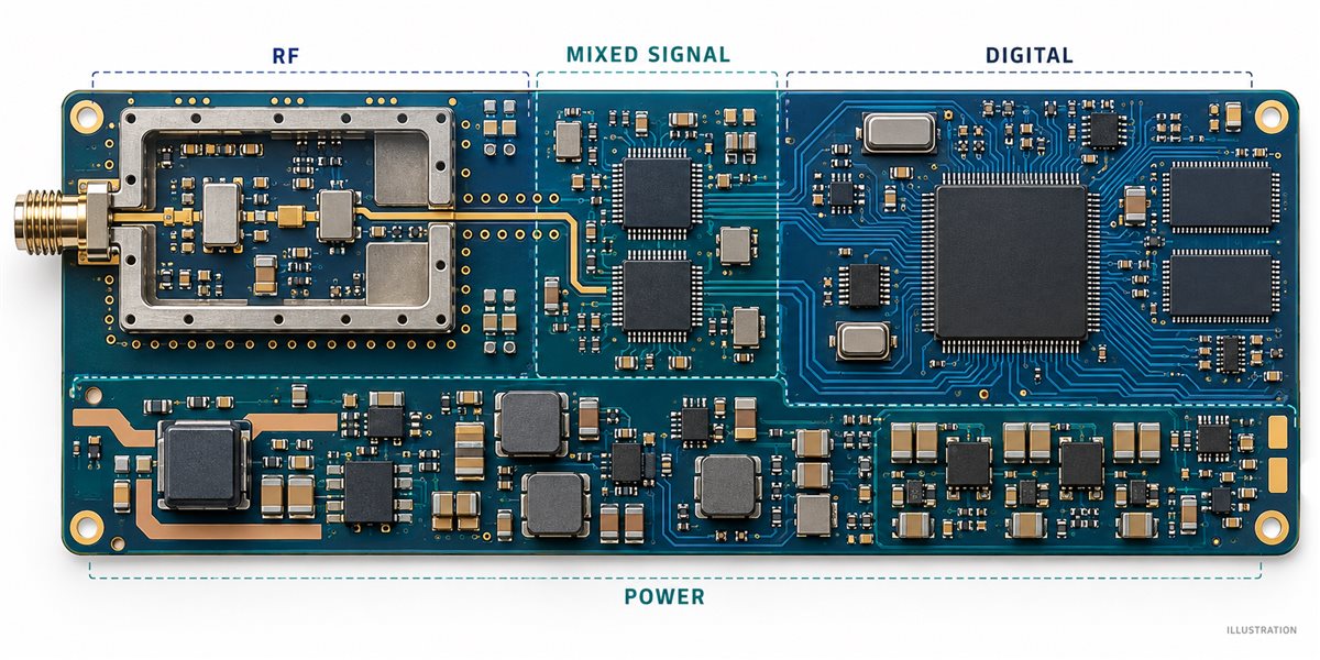
The RF front end, data-conversion section, digital modem logic, and aircraft interfaces are separate acceptance boundaries even when they share one PCB. An RF trace may meet its drawing while a clock spur, power ripple, cable launch, or enclosure bond degrades system performance. Conversely, a working digital self-test does not prove antenna-path behavior. The OEM should identify the reference planes, controlled-impedance nets, connector launches, shield interfaces, clock sources, supply rails, programming files, and the external equipment used in the intended integration test.
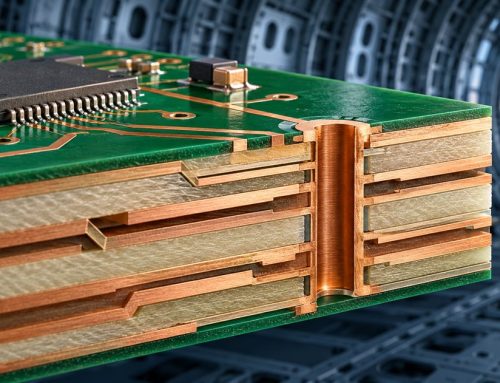
For the bare board, release the stackup, dielectric material or approved alternatives, copper requirements, controlled-impedance geometry, fabrication notes, test coupons, and acceptance method. The actual RF geometry depends on the approved design and material set; it should not be inferred from a generic “50-ohm PCB” purchase description. Our controlled-impedance RFQ guide explains how to name the critical nets, stackup, and acceptance evidence, while the RF PCB overview gives broader material and layout context. Analog Devices’ RF and mixed-signal layout guidance likewise treats return paths, coupling, component placement, and power decoupling as design-specific concerns.
The factory scope also needs an explicit boundary. Decide whether the EMS order ends at assembled PCBA, includes programming and RF alignment, includes shields and enclosure assembly, or includes a test fixture and serialized evidence package. The supplier can execute an agreed procedure; the OEM owns the limits, approved configuration, and interpretation of system-level compliance.
Release the design package as one configuration
A SATCOM modem board should not be ordered from a BOM alone. A useful release package links the PCB fabrication revision to the assembly drawing, component list, firmware or FPGA image, test software, connector interface, and approved substitution rules. Otherwise a technically correct component procurement change can alter RF gain, phase noise, clock behavior, thermal dissipation, or digital timing without a corresponding test update.
Use the matrix below to assign the release decision and the evidence required at handoff. It is a procurement planning example; the OEM’s controlled documents and applicable approval plan determine the actual records.
| Boundary | Release input | Supplier evidence | OEM decision before build |
|---|---|---|---|
| RF PCB and launches | Stackup, critical nets, material, RF connector and shield drawings | Fabrication revision, coupon or agreed impedance evidence, connector inspection | Accept the exact stackup and launch geometry |
| Components and alternates | Approved BOM, manufacturer part numbers, no-substitution list | Lot/source records and deviation requests | Approve any RF, clock, converter or power change before placement |
| Digital configuration | Firmware/FPGA image, programming method, hardware compatibility map | Program log and readback identifier | Approve the image-to-PCBA revision pairing |
| Power and thermal | Rail limits, heat-spreader interface, test load and ambient condition | Defined electrical and fit test results | Set pass/fail limits and integration conditions |
| Test and shipment | Fixture revision, RF test plan, traceability and packaging rules | Serial-linked inspection and test record | Approve what counts as board acceptance versus equipment qualification |
Revision control is especially important when the modem uses programmable logic. FAA AC 20-152A has scope and objectives for airborne electronic hardware, including circuit board assemblies and, where applicable, custom devices. The applicability of those objectives depends on the program and hardware function; an EMS supplier should not promise a development-assurance level or certification from a generic PCBA quotation.
Qualify RF-to-digital integration before the production quote
The pilot build should answer whether the released board, components, software image, fixture, and test limits behave together under the OEM’s defined conditions. Place the first builds behind a controlled deviation process, not an informal “tune until it works” loop. Record the build revision, serial number, fixture revision, instrument setup, calibration status where required, software version, and test-condition identifiers so that a later RF result can be reproduced.
For RF measurements, the OEM should state the required stimulus, measurement point, connector/cable treatment, temperature or supply condition, and pass/fail limit. Depending on modem architecture, relevant measurements might include gain or loss, frequency error, spurious response, error-vector magnitude, or bit-error performance. This is a menu of possible test categories, not a specification for every SATCOM board. If the supplier is expected to perform alignment, the calibration procedure, approved adjustments, and retest rule must be part of the release.
When the BOM, stackup, fixture, and test responsibility have been settled, teams can share the controlled PCB, BOM, and test package for scope review. Include pilot quantity and identify which RF measurements the OEM will perform so fabrication, sourcing, assembly, and fixture work can be assessed against the same boundary.
Control the changes that can invalidate an RF result
The change list for a mixed RF/digital assembly is broader than the component price file. A laminate substitution can change electrical behavior; an RF connector or shield change can alter a launch or return path; a clock, converter, regulator, or firmware change can change the noise or timing environment. The correct rule is not “never substitute.” It is to identify which changes require the OEM’s engineering review and which acceptance evidence must be repeated.
Use an approval matrix tied to the measurement it might affect. For example, a proposed RF laminate alternative needs comparison to the controlled material properties and stackup, followed by the OEM’s chosen coupon or RF retest. A replacement clock component needs electrical compatibility review and the OEM-defined spectral or timing test. A programming image update needs a version/readback check and the relevant functional regression test. Treat these as examples; the design authority determines the actual critical characteristics and limits.
The mixed-signal layout discussion from Analog Devices explains why digital switching and analog/RF return paths need considered placement and grounding rather than a universal split-plane prescription. This makes the layout review and the as-built stackup as important as the parts list. Any engineering change should identify its affected revision, first serial number, disposition of work in progress, and required retest before the next batch moves.
Separate PCBA inspection from modem and aircraft acceptance
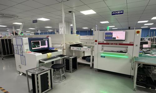
EMS inspection is a valuable manufacturing gate, but its evidence must be labeled at the level it actually proves. Automated optical inspection (AOI) can check visible placement and solder features on an assembled board; it cannot by itself establish RF performance, environmental qualification, installation compatibility, or airworthiness approval. The OEM should define board-level electrical and RF tests, then separately define equipment-level and installation-level activities.
| Gate | What it can answer | Typical evidence to request | What it does not prove alone |
|---|---|---|---|
| Fabrication and assembly | Was the specified PCB and population built? | Fabrication/assembly revision, inspection record, traceability, approved deviations | RF link performance |
| Program and board test | Was the correct image loaded and did the board meet released board limits? | Readback ID, fixture version, serial-linked electrical/RF results | Aircraft installation suitability |
| Integrated equipment test | Do board, enclosure, harness, cooling and external interfaces work together? | Equipment configuration and OEM-defined functional test record | Approval for all aircraft or environments |
| Environmental and approval activity | Does the equipment meet the selected program requirements? | Applicable plan, selected categories, qualified test reports and approval records | A generic claim that every PCBA is certified |
RTCA describes DO-160 environmental test methods for airborne equipment. Those methods do not assign one universal set of categories to every board; the applicable equipment and installation program must select the conditions and acceptance criteria. Our environmental test selection guide explains why specifying a method without a severity, sample, and pass/fail rule leaves the purchase order incomplete.
Ask for a quote that exposes test and ownership assumptions
A useful EMS comparison prices the same controlled boundary from each supplier. Provide fabrication data, stackup and impedance requirements, approved BOM and alternates, placement/assembly files, programming instructions, quantity breaks, board test plan, RF fixture and instrument responsibilities, traceability rules, and the desired packaging condition. State whether any shielding, coating, mechanical integration, or environmental test is included. If the OEM has not released an RF acceptance method, request a separate engineering work package rather than silently bundling undefined test into unit price.
Ask bidders to identify long-lead or source-restricted RF parts, fixture nonrecurring engineering, pilot-build quantity, and the specific evidence they can return with each unit. A lower assembly quote may exclude programming, RF calibration, or serial-level records. A more expensive quote may include those gates; comparing only the per-board price hides the program decision. Our PCB assembly service overview describes the manufacturing scope that can be evaluated, but each SATCOM-specific requirement still needs confirmation against the actual design and quotation.
The practical release decision is to approve a traceable pilot configuration, close its RF/digital and mechanical interfaces, and accept each test at the correct level. If the project package is ready, provide the released files and acceptance responsibilities together with build quantity and target schedule. That lets the team review fabrication, component sourcing, assembly, programming, and test assumptions as one scope before pricing the next build.
Latest Blog

Contact Info
Phone: +86-755-82882936
Email: [email protected]
WhatsApp: +86-13570802455
Wechat: +86-13570802455
Address: 2nd floor,D Bldg.,Electric Link Technology Bldg.,Gongming,Guangming New Dist.,518106 Shenzhen, China