
406 MHz ELT Beacon PCB Design: Verify Power During the RF Burst
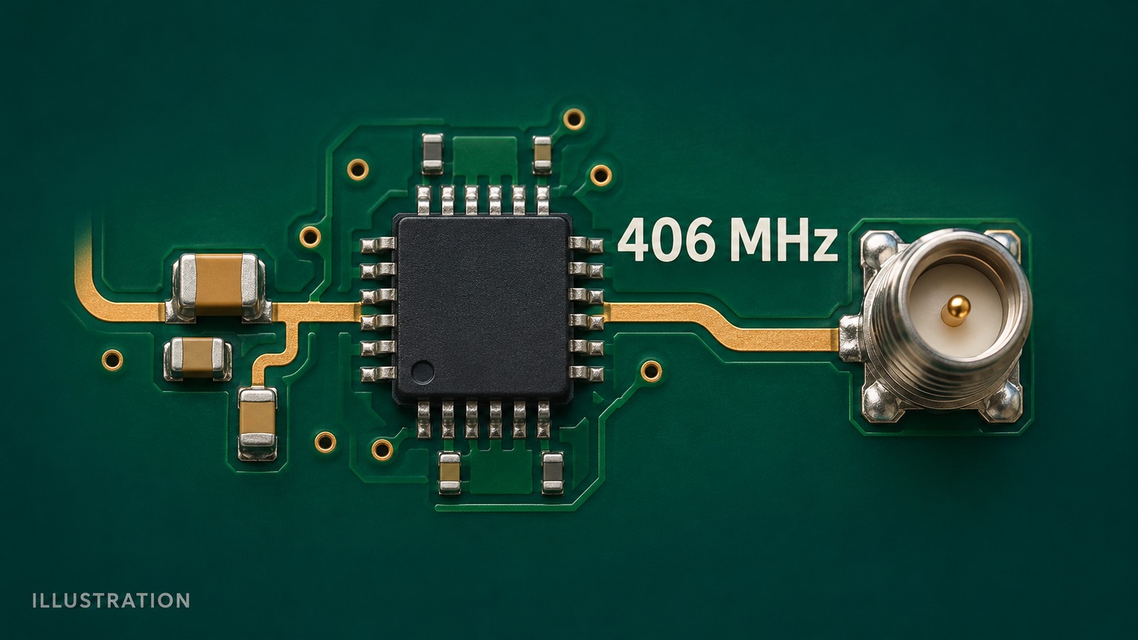
Table of Conent
Table of Conent
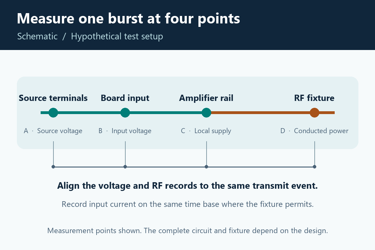
For a 406 MHz emergency locator transmitter (ELT) PCB, verify burst power by recording source voltage, board input voltage, and the radio-frequency (RF) power amplifier supply during the same transmit event. Where the approved fixture permits a conducted test, capture RF output at a defined measurement plane as well. A weak source, resistance in the power path, a sagging amplifier rail, and an error in the RF fixture can all produce a low reading. Aligned measurements show where to look first.
Use this approach to turn design characterization into an assembly acceptance test with known coverage. Set source conditions, limits, and the approved transmission mode with the beacon design authority. The production fixture should reproduce the board-level conditions it claims to verify, and the qualification plan should identify the representative equipment configuration.
Define the beacon conditions the board must support
Start with the approved power source, the operating mode, and the RF measurement boundary. These three decisions determine which observations a board test can support. Record them on the test drawing and use the same identifiers in the lab data and production results.
An ELT is the aircraft type of emergency distress beacon. A production test must prevent a distress transmission from entering the search-and-rescue system. Follow the manufacturer’s authorized test procedure and the program’s RF containment and test-mode requirements. The NOAA guidance on emergency beacon testing explains the difference between the beacon’s prescribed self-test and transmissions that need coordination. Use a controlled fixture under an approved test procedure for any conducted burst measurement discussed here.
Define the source state in terms that another lab can reproduce. For an actual pack, identify the approved configuration, temperature, conditioning, and starting state. For a source emulator, specify the validated voltage and time-dependent response at the board input. A bench source set to the nominal open-circuit voltage can still present a different pulse response from the battery and harness in the product. Specify both the first burst and any repeat-burst condition that the program needs to evaluate.
The FAA guidance on DO-160 environmental qualification describes environmental testing at the airborne equipment level. The program determines the applicable edition, categories, modes, and pass criteria. If the enclosure, antenna path, mounting, or cable affects the result, identify that dependence in the test plan. The assembly test record should state the board revision, programmed image, fixture, and observed results so the design authority can determine which evidence supports the larger qualification program.
Measure the burst at the source and the amplifier
Capture one time-aligned record that shows the source terminals, the board input, the amplifier rail, and the measured RF envelope. If practical, record input current and a timing reference on the same acquisition. A minimum voltage and a single power number can hide whether the problem started at key-up, developed during the burst, or followed a reset.
Use suitable probes and define the return at each measurement point. A long probe ground, an added current shunt, or a fixture lead can alter the observed transient. Use a validated reference board to check setup repeatability before comparing production boards. Record the test cable and source configuration so a future run can distinguish a board change from a fixture change.
| Observed pattern | First area to investigate | Useful follow-up evidence |
|---|---|---|
| Source terminals sag with load | Pack or emulator response | Compare current and source voltage against the approved source profile and conditioning. |
| Source holds while board input drops | Harness, contacts, protection, or distribution path | Measure the drop across candidate segments at the same instant in the burst. |
| Board input holds while amplifier rail dips | Local regulation and decoupling | Compare load timing with recovery and check for regulator current limit or a board population change. |
| Supply rails hold while reported RF falls | Transmit control, RF chain, or measurement fixture | Check keying and verify the fixture with an approved RF reference before changing the board. |
The rail can show a short edge dip and a longer recovery interval. Texas Instruments’ analysis of LDO load transients describes how capacitance, equivalent series resistance (ESR), and regulator response shape the transient response of a low-dropout (LDO) regulator. Apply that reasoning only to the actual regulator topology and measured loading. If fixture access is still open, share the burst envelope and measurement points with the board drawing so the assembly team can review access, tooling, and which waveforms the test would retain.
Separate power droop from RF path and fixture losses
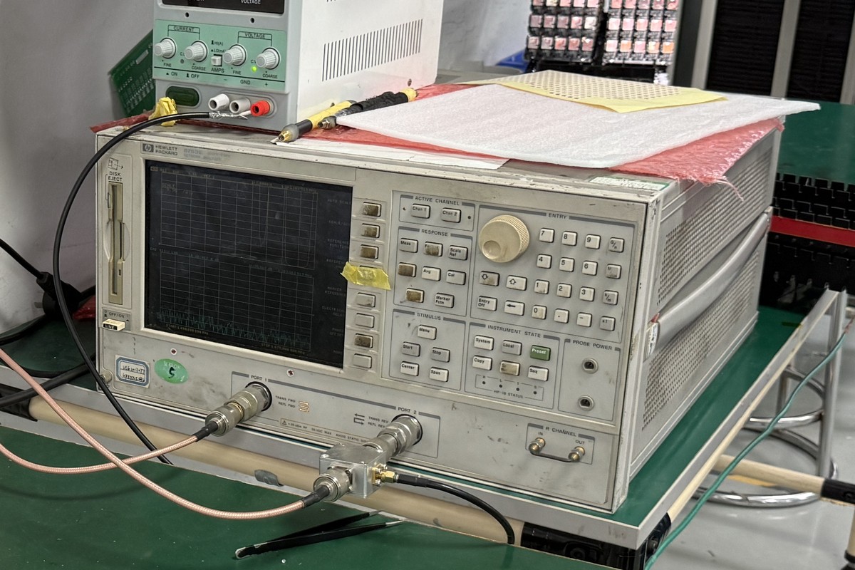
Define the point to which the power reading applies and verify the measurement chain at that point. If the fixture reads downstream of a cable, attenuator, or coupler, use the approved calibration and correction for that path. A constant error in the path can shift every board by the same amount.
Record the attenuator, cable set, instrument range, calibration identity, and the test’s power measurement window. Validate that the instrument and fixture can capture the specified part of the burst without overload or inappropriate averaging. For a model-specific example of why test configuration matters, the ARTEX ELT 345 service documentation includes a service procedure that uses an attenuator to protect its measuring equipment. Component ratings and connections for a different beacon must come from that beacon’s approved test plan.
For example, suppose a verified reference board and the test unit both read low after a cable replacement, while their supply waveforms still agree with the previous run. Investigate the fixture reference before rejecting either board. If the fixture reference remains stable and only one assembly shows a late-burst rail dip followed by RF loss, check the assembly’s local power path and fitted parts. Retain the aligned traces from both runs to support that diagnosis.
Use manufacturing test coverage for complex PCBAs to assign inspection, programming, and functional checks to the right station. Optical inspection can help verify placement or visible joints. The conducted test adds evidence about electrical behavior at the approved operating point. Record which checks run on each unit and which ones are reserved for characterization or change approval.
Control parts that change burst performance
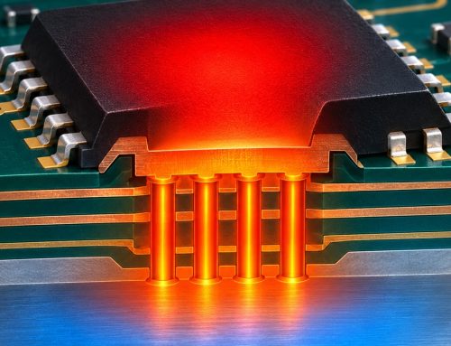
Review alternate parts by the electrical behavior they can change during a burst. A same-footprint capacitor can change the available capacitance at operating voltage. A connector, protection device, or battery revision can change the effective impedance seen by the transmitter.
| Proposed change | Burst variable affected | Targeted evidence |
|---|---|---|
| Battery pack, contacts, or harness | Source droop or voltage loss before the board | Compare source-to-board drop and burst current at the approved source conditions. |
| Bulk or local capacitor | Effective capacitance, ESR, and rail recovery | Review part data at actual voltage and temperature, then compare the aligned rail and power captures. |
| Regulator or input protection | Transient response, current limit, or voltage headroom | Repeat the applicable pulse sequence and check voltage minima and recovery against approved limits. |
| RF launch, connector, or stackup | Transmission loss or match at the measurement boundary | Check the relevant RF path and the product’s conducted result with the validated fixture. |
Give purchasing a part-specific rule. For ceramic storage or bypass components, checking MLCC DC bias before approving capacitor alternates helps identify changes that a catalog capacitance match can miss. Record manufacturer part numbers and approved alternates in the BOM. When a proposed change affects the approved equipment configuration, send the board evidence to the design authority for a disposition before release.
Specify the ELT board build and acceptance package
Put fabrication, sourcing, assembly, and functional test into one project scope with separate deliverables and acceptance criteria. Procurement can then compare what each supplier included in the build, fixture, programming, and per-unit test price.
Provide fabrication data and stackup, a BOM with alternate rules, placement data, assembly drawings, quantity, and delivery requirements. Add the controlled firmware, source profile, approved test mode, RF reference plane, and the minimum evidence each result must include. Identify who supplies the fixture and reference unit, who checks calibration, and what happens to the original data when a unit fails or is retested.
The turnkey PCB assembly scope gives a starting point for coordinating fabrication, parts, and assembly. Where the released package is ready, send the released board files and test scope with the requested fixture and result deliverables so the team can assess test coverage and price the complete build.
Release against the complete burst record
Accept a production board using its approved limits and the evidence defined for its configuration. Keep the source, rail, and RF observations tied to the same event when they are required. Trace the result to the board serial, hardware and firmware revisions, and fixture. That record gives the next engineer a way to reproduce a marginal burst and decide whether the next investigation belongs at the source, the assembly, or the RF measurement chain.
Latest Blog





Contact Info
Phone: +86-755-82882936
Email: [email protected]
WhatsApp: +86-13570802455
Wechat: +86-13570802455
Address: 2nd floor,D Bldg.,Electric Link Technology Bldg.,Gongming,Guangming New Dist.,518106 Shenzhen, China
