
CNC Controller PCB Design: Timing, Isolation, and Build Tests
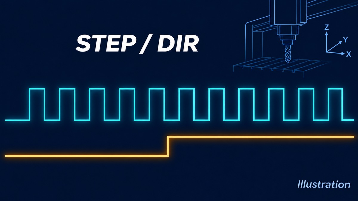
Table of Conent
Table of Conent
CNC controller PCB design starts with the electrical contract between the motion planner, axis drives, spindle interface, and machine controls. Define where pulse generation ends, where motor current flows, and which circuits own stopping and restart. Then check STEP and DIR at the receiving input, including startup and supply-loss conditions. A clean waveform at the microcontroller pin does not establish that a remote drive receives the same timing.
For a board going into production, capture those decisions in the schematic, approved parts list, connector map, and acceptance plan. Isolation needs its own power and return-path review. Integrated motor drivers need layout and thermal checks tied to the actual load. Assembly inspection needs separate electrical tests for pulse timing and output defaults. This guide focuses on pulse-interface controllers and their manufacturing handover. Networked servo systems require additional protocol and synchronization analysis, while machine safety validation remains a separate, explicitly assigned system responsibility.
Choose the motion and power boundaries first
Choose an architecture by assigning pulse generation, power conversion, feedback, and protection to named hardware. That assignment determines the board’s electrical interfaces and the evidence needed before fabrication.
An integrated controller includes the axis power stages on the PCB. Its design must address winding current, switching loops, heat flow, connector loading, and supply behavior. A motion or breakout board connected to external drives instead needs a precisely specified command interface. Copying an integrated-driver layout onto a breakout board confuses these responsibilities and can add unnecessary power circuitry.
For each axis, identify the exact drive and receiving input. Record whether the connection is single-ended, differential, or an optocoupler input requiring a specified current. Define polarity, voltage limits, cable arrangement, reference conductor, and connector pin numbering. A label such as “5 V STEP” leaves several of these questions unanswered.
Include spindle command and feedback separately. An analog speed command, a PWM interface, a relay contact, and a communications link need different circuitry and tests. Keep a connector-level interface drawing under revision control so procurement, firmware, board layout, and fixture development use the same assumptions.
Budget STEP and DIR timing at the receiving input
Set the pulse rate from the commanded motion, then verify pulse widths and command timing against the receiving device’s requirements. Average frequency alone cannot establish a valid interface.
For a stepper example, assume 200 full steps per revolution, 16 commanded microsteps per full step, and a maximum motor speed of 5 revolutions per second. The required STEP rate is 200 × 16 × 5 = 16,000 pulses per second, giving a 62.5 µs period. These are illustrative inputs, not recommended CNC settings. The calculation predicts commanded electrical increments; it does not establish mechanical positioning accuracy or available torque.
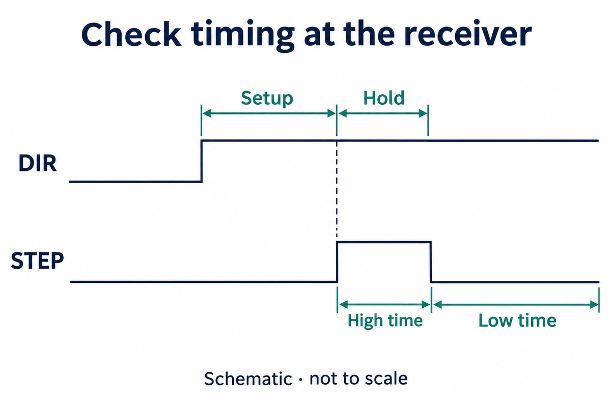
The DRV8825 timing requirements provide a device-specific example: STEP high and low durations each have a 1.9 µs minimum, while command setup and hold around the rising edge each require 650 ns. Enable and wakeup have separate requirements. Apply the actual selected driver’s datasheet and operating conditions rather than extending these limits to another IC or external drive.
| Check | Design question | Evidence to retain |
|---|---|---|
| Pulse high and low | Do both intervals meet receiver limits after conditioning? | Worst-case received widths and their limits |
| DIR setup and hold | Does direction remain stable around the sampling edge? | Relative STEP/DIR timing at reversals |
| Enable and wakeup | Is the first step delayed until the receiver accepts it? | Startup and re-enable captures |
| Concurrent axes | Do scheduling and shared resources preserve each channel? | All-axis pattern, firmware identity, and pulse counts |
Budget uncertainty through the complete path. Different delays on STEP and DIR reduce their relative timing margin; unequal rising and falling delays can alter pulse width. Include specified delay variation, firmware scheduling, and the selected receiver thresholds. Review minimum and maximum conditions rather than subtracting one typical isolator delay from the period.
Use an edge-rate and return-path review when the interconnect behaves as a transmission line. Select any damping or termination from the interface and observed waveform. A universal series-resistor or ferrite prescription cannot account for every cable and receiver.
Once these interface choices are fixed, share the interface drawing and controlled parts list with the assembly package so sourcing alternatives and the required build checks can be reviewed together.
Specify isolation as a complete electrical boundary
Isolation requires a defined signal barrier, power arrangement, and return map. Every connection crossing the boundary must be accounted for, including connections introduced during programming and testing.
Mark logic-side and field-side references on the schematic and connector drawing. Review isolated power, shields, mounting connections, debug cables, and fixture grounds. A temporary programmer or measurement connection can bridge references that the finished design keeps separate. The test arrangement should preserve the intended boundary or explicitly document the changed condition.
Check output behavior as carefully as signal speed. TI’s ISO774x function table distinguishes default-high devices from default-low F-suffix options. Output disable can produce high impedance, and loss of output-side supply has a different defined condition from loss of input-side supply. Capture the exact order code and external biasing in the approved BOM.
As a proposed release check, record STEP, DIR, and enable behavior during normal operation, controller reset, each relevant rail-loss condition, and power restoration. Set the expected result from the circuit and machine requirements. Substitutions should trigger a review of defaults, timing, package, and isolation ratings before purchasing approval.
Keep power-current loops separate from sensitive measurements
For integrated drives, place the switching and decoupling paths around the power stage, then protect current-sense and logic returns from those currents. For external-drive interfaces, preserve the specified signal return and connector arrangement.
TI’s motor-driver layout guide explains placement, grounding, power routing, and current-sense routing as related design decisions. Short local switching loops and appropriately placed capacitors reduce parasitic effects. Sense connections should measure the intended shunt voltage rather than include unwanted power-path drops. Apply the selected topology’s reference layout and verify it against the actual stackup.
Carry those decisions into fabrication instructions. Identify copper construction, stackup, thermal features, exposed-pad requirements, and any isolation keepouts that affect production. Check solder-mask openings, stencil strategy, and inspection access with the assembler. A thermal pad that works in the CAD model still needs a buildable soldering and inspection plan.
Separate component ratings from assembly capability. Driver current depends on the device, thermal path, operating conditions, and enclosure. Validate the intended duty cycle and cooling arrangement before treating a catalog maximum as a board-level continuous rating. Record the tested board revision, load, ambient conditions, mounting, and temperature measurement locations so another build can reproduce the assessment.
Define stop and restart behavior at machine level
Assign the machine’s stop functions to an approved system architecture and document the controller’s role within it. An ordinary enable output or firmware command does not establish a safety-rated stopping function.
Pilz’s drive-technology guide distinguishes safe torque off from controlled stopping and addresses gravity-loaded axes. Removing torque can allow a moving axis to coast; suspended loads can require additional measures. The appropriate function, monitoring, braking, and validation depend on the machine risk assessment and selected equipment.
At the PCB interface, document signal polarity, loss-of-power behavior, reset conditions, and the distinction between status reporting and the actual stopping path. Identify who approves the schematic, who validates machine behavior, and which records the board assembler must provide. Keep the production test specification within that assigned scope.
Use approved simulations and fixtures to check board outputs, input reporting, and restart conditions without turning a routine assembly test into an improvised machine test. Record abnormal-state observations against the requirement that defines acceptance. A passed board test supports its stated coverage; it does not certify the complete CNC machine.
Release measurable tests with the manufacturing files
Release the board files and test definition as one controlled configuration. The assembler needs observable acceptance criteria and the tooling scope needed to produce them.
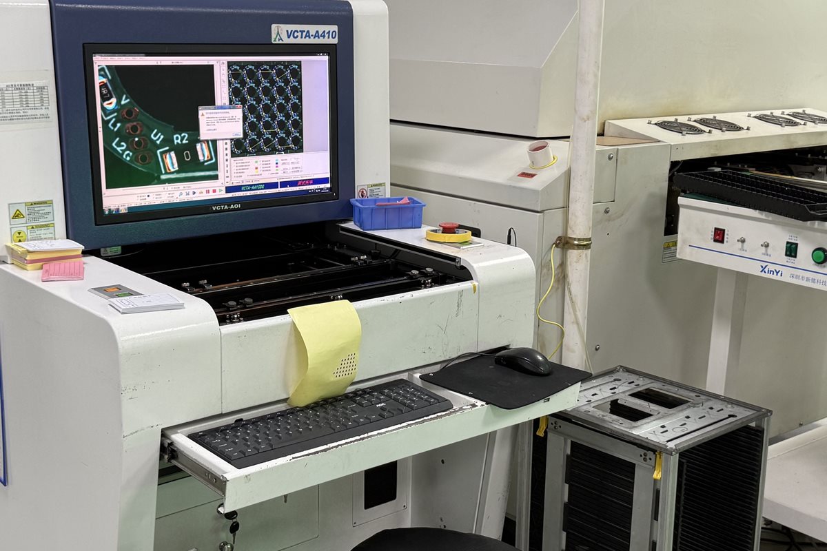
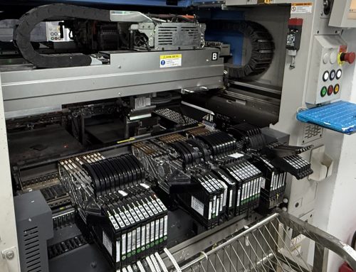
Plan manufacturing test coverage around the faults and interfaces that matter. Optical inspection can check visible assembly features, while powered tests address signal timing and behavior. Hidden-joint inspection, programming, and fixture access should be specified where the design requires them.
| Scope | Conditions to define | Recorded evidence |
|---|---|---|
| Pulse interfaces | Receiver, cable or load, concurrent-axis pattern, limits | Timing results, counts, and firmware revision |
| Startup and rail loss | Approved supply sequence, reset states, expected outputs | Observed states and recovery result |
| Power stage, if fitted | Load, duty cycle, mounting, cooling, acceptance limits | Electrical and thermal results under those conditions |
| Repeat-build identity | Board, BOM, firmware, fixture, and procedure revisions | Serial-linked results and disposition of failures |
The official OrinewPCB video below illustrates general Gerber manufacturability issues relevant to the fabrication review. Use the released design and agreed process rules for the actual board’s dimensions and acceptance criteria.
Separate fixture development and first-build correlation from recurring unit tests in the PCB assembly cost and scope review. Define which checks repeat on every unit and which belong to engineering validation. Agree how fixture changes and component substitutions affect requalification.
A usable CNC controller release preserves receiver timing, electrical boundaries, and configuration identity across builds. For an upcoming project, provide the released board files and acceptance plan, including Gerbers, BOM, placement data, quantities, and sourcing constraints, so OrinewPCB can assess fabrication, component procurement, assembly, and agreed testing within one project scope.
Latest Blog


Contact Info
Phone: +86-755-82882936
Email: [email protected]
WhatsApp: +86-13570802455
Wechat: +86-13570802455
Address: 2nd floor,D Bldg.,Electric Link Technology Bldg.,Gongming,Guangming New Dist.,518106 Shenzhen, China
