
Case Packer Controller PCBA: Control BOM Substitutions and Functional Test Coverage
Table of Conent
Table of Conent
A case packer controller PCBA is ready for a comparable assembly quote when the machine owner has released both a controlled component list and a board-level test specification. If an encoder receiver, isolated input, output driver, or fieldbus part can be substituted, the owner should define the approval boundary before sourcing begins. If the RFQ says only “functional test,” each assembler may price a different fixture and acceptance scope. The useful comparison is therefore not just assembly price: it is the same approved material configuration, the same observable board functions, and the same evidence at shipment.
This article addresses a controller board supplied to a case packer OEM. It does not assume that the board contains the servo power stage, that every case packer uses the same number of axes, or that a board-level pass validates a guarded machine. Those details depend on the released architecture.
Release the BOM as an approval system, not a list of possible parts
A useful BOM distinguishes a released manufacturer part number, an owner-approved alternate, and a supplier proposal that still needs engineering disposition. An approved vendor list (AVL) may name multiple parts, but it should also identify the assembly revision and any conditions under which each part is allowed. A distributor cross-reference alone is not an engineering approval.
For a case packer controller, substitutions can change an electrical interface even if package and pinout match. Consider the encoder receiver’s input threshold and termination, an isolated I/O component’s timing and isolation rating, or a fieldbus transceiver’s electrical behavior. The OEM should compare the actual datasheets against the circuit and operating envelope, then record the decision against the board revision. The BOM alternate approval workflow explains how to keep that decision attached to a controlled release.
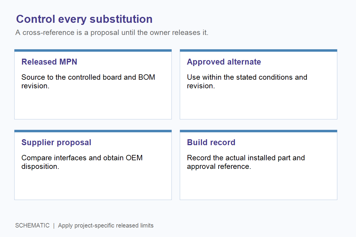
Before requesting a quote, mark no-substitution lines, conditional alternates, do-not-populate positions, firmware-dependent variants, and parts supplied by the OEM. For each line, include manufacturer part number, quantity per board, reference designators, package, and revision. Match the placement file and assembly drawing to that same revision. This prevents a procurement assumption from becoming a silent engineering change.
| Material status | What the assembler may do | Evidence the buyer should receive | Quote treatment |
|---|---|---|---|
| Released MPN, available | Source the specified part through the agreed channel | Purchased MPN and lot or date-code record at the agreed traceability level | Include in the base quote |
| Owner-approved alternate | Use only under the stated board revision and conditions | AVL approval reference and actual installed part | Identify whether priced as base or option |
| Supplier-proposed alternate | Hold use pending OEM engineering disposition | Datasheet comparison and approval or rejection record | Price separately until approved |
| No-substitution line | Do not replace without a new controlled release | Exception or shortage notice before build | State schedule and inventory assumptions |
The traceability depth is a contract decision, not a universal per-component rule. IPC’s description of IPC-1782 ties manufacturing and supply-chain traceability to perceived risk agreed between user and supplier. Apply more detailed records where a part or process affects the OEM’s diagnosis, service life, or safety case.
Price sourcing assumptions separately from assembly labor
A quote should make component availability, purchase quantity, ownership of excess inventory, and approved sourcing channels visible. These assumptions can change total cost without changing a single placement operation. The buyer should compare an assembler’s proposed buys against the released BOM and expected production stages, rather than treating all price differences as labor efficiency.
Ask which parts are purchased for the pilot lot, which are bought in larger packaging, and who owns remaining material. If a part is constrained, require a named disposition path: approved alternate, owner-supplied material, revised schedule, or design change. Do not accept an unreviewed broker purchase as an invisible quote assumption. A purchasing record should connect the actual part and source to the board configuration that was tested. The MLCC alternate assessment offers a concrete example of why identical nominal values do not prove equivalent in-circuit performance.
At this point the OEM has enough information to expose sourcing ambiguity. If the build is moving from prototype to pilot, share the released BOM and substitution rules for review with the fabrication files, placement data, and planned quantity. The next useful response is an explicit material and assembly scope, including any proposed alternatives that need owner disposition.
Specify functional coverage by interface and evidence
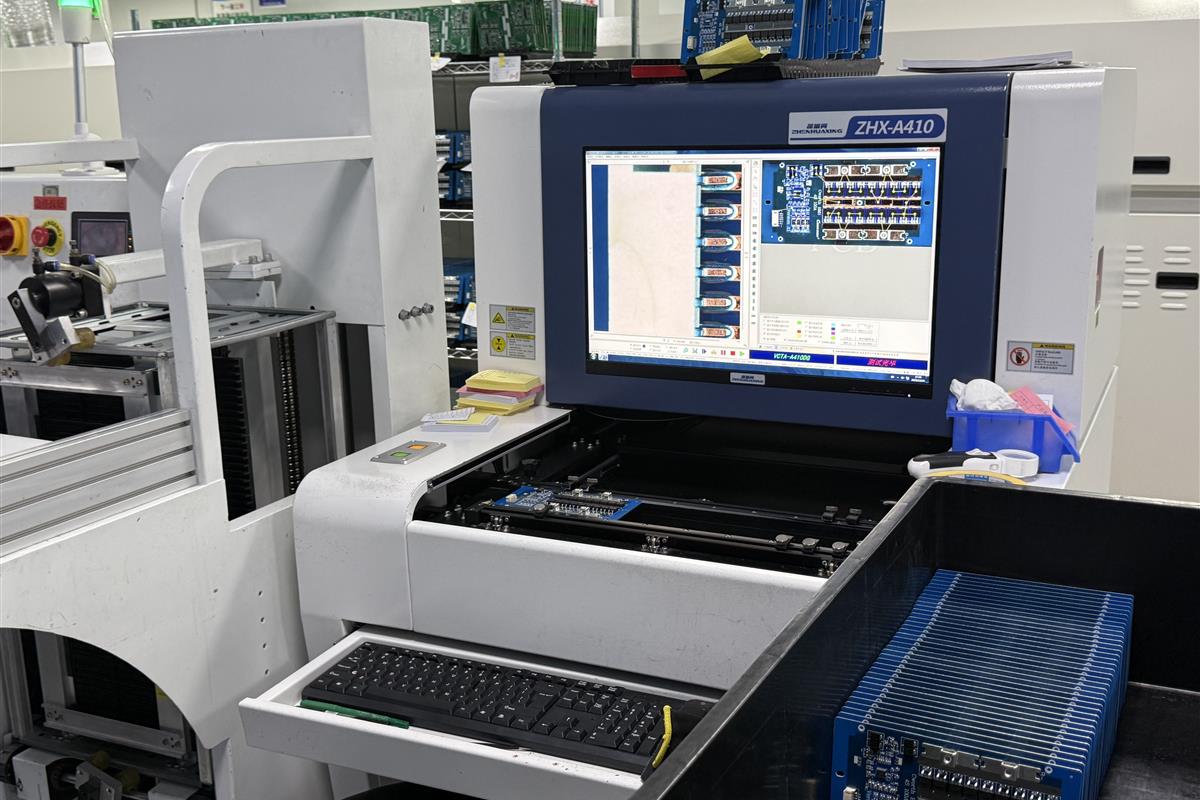
AOI and other structural checks can detect many assembly defects, but they do not show that every controller interface performs under its intended stimulus. Board functional test should identify each released input, output, supply, communication path, and programmed state, along with the stimulus, limits, and recorded result. The fixture may use simulators rather than a complete case packer, provided that the simulation represents the interface being accepted.
Encoder interfaces illustrate why the board architecture matters. A quadrature A/B input, an RS-422 differential receiver, and a serial absolute-encoder interface need different stimuli. Analog Devices’ motion-feedback guidance discusses the RS-422 receiver and cabling system, while Texas Instruments’ eQEP report describes counting modes and interface choices. Neither source supplies a universal test frequency for every case packer. The OEM should provide the released signal format and operating limits.
| Controller function | Representative fixture stimulus or load | Evidence to record | Boundary or omission decision |
|---|---|---|---|
| Power rails and reset | Defined supply range and representative load | Voltage, current, startup and reset behavior against released limits | State whether loaded measurement is included |
| Encoder or position input | Released signal type, direction and edge conditions | Count, direction, fault indication or protocol response | Specify interface type; do not assume one simulator fits all variants |
| Digital and isolated I/O | Released input levels and representative output loads | State transitions, polarity and fault response | Define whether isolation is measured separately |
| Network or fieldbus | Known partner device or specified test node | Link establishment and required messages | State whether loopback alone is acceptable |
| Firmware and configuration | Released image and controlled parameters | Program version, checksum or other owner-defined identity | Separate programming from execution of the functional sequence |
The table is a scope template, not a claim that assypcb.com already owns a fixture for this product. The OEM and assembler must agree on fixture design, test limits, serial-number logging, retest disposition, and ownership of test software before the line item is comparable. The broader PCBA testing process guide provides context for structural and electrical test stages.
Keep safety-related board observations separate from machine validation
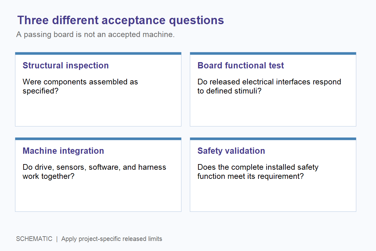
A fixture can verify that a safety-related input or output changes state at the board connector under defined conditions. That observation does not establish the performance of the complete guard, drive, brake, wiring, software, and machine. The system owner must define the relevant safety function and validate it in the actual architecture.
For example, a board may expose an enable signal to a drive with Safe Torque Off. A board test can verify the released signal path and fault indication. It cannot by itself prove safe stopping behavior of the installed machine. Rockwell Automation’s Safe Torque Off manual assigns system-level risk assessment, connected-sensor validation, configuration and proof testing to the system user. Apply the machine’s own applicable requirements and qualified safety review; avoid writing a generic PCBA test result as a machine safety certificate.
The distinction matters at purchase order release. If a supplier quotes only PCBA fabrication, assembly and board functional test, the OEM should retain ownership of machine commissioning and integration acceptance. If a larger integration package is requested, document the extra harness, drive, sensor, software and validation deliverables separately.
Send a controlled RFQ package that makes quotes comparable
A useful case packer controller RFQ pairs the build definition with a test boundary. Supply the fabrication outputs, BOM and AVL, centroid or pick-and-place file, assembly drawings, firmware and programming instructions, target quantities, material ownership rules, and board test specification. Identify any safety-related interface that requires separate system validation. Ask each supplier to list exclusions, assumptions and one-time fixture work before comparing totals.
For a coordinated fabrication, sourcing and assembly review, the full turnkey PCB assembly service is the relevant commercial path; its scope should still be confirmed against the released package. When the files and acceptance criteria are ready, provide the board files and test boundaries for project review so the next step can identify BOM exceptions, fixture work and the quote scope rather than hide them in a single price.
For a separate example of how an approved change can reduce BOM cost after product release, OrinewPCB’s short video below outlines three low-risk approaches. Apply any proposed alternate only through the controller’s documented approval boundary.
The release decision is straightforward: freeze what may be built, identify who can approve a substitution, and specify what a passing board must demonstrate. That gives procurement a meaningful comparison and gives engineering a traceable boundary between a tested PCBA and an accepted case packer.
Latest Blog
Contact Info
Phone: +86-755-82882936
Email: [email protected]
WhatsApp: +86-13570802455
Wechat: +86-13570802455
Address: 2nd floor,D Bldg.,Electric Link Technology Bldg.,Gongming,Guangming New Dist.,518106 Shenzhen, China