
Capping Machine PCBA: Sequence SMT, Through-Hole, Test, and Coating
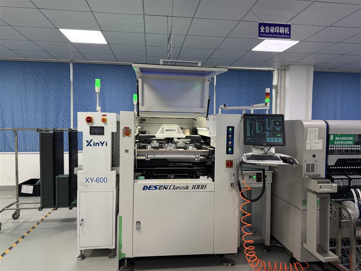
Table of Conent
Table of Conent
A capping machine PCBA should be quoted and released against the actual assembly, test, and coating sequence—not a bare board drawing alone. For a controller that combines fine-pitch control electronics with connectors or power components, the build package should identify which parts are SMT, which are through-hole, what must remain accessible for programming and test, and whether a protective coating is required. The approved sequence depends on the design and the coating process; there is no universal capping-machine recipe.
The practical decision is whether the supplier can prove electrical operation before any coating obscures inspection or access, then show that masking, application, cure, and any required retest were completed against the same board revision. A machine-level cap-torque or safety result remains the equipment maker’s validation, even if the board passes its fixture.
Freeze the assembly inputs before choosing a process route
Start with the PCB revision, fabrication files, assembly drawings, approved BOM and alternates, firmware image and revision, connector pinout, and expected test loads. Identify whether the controller receives sensors, drives a motor interface, or merely exchanges commands with separate drives. These distinctions change the fixture and acceptance limits. The assembly drawing checklist helps locate polarity, connector orientation, and special handling instructions that a placement file cannot settle.
Do not assume a servo drive, torque sensor, or safety circuit resides on the PCBA because the finished machine has one. Record the actual board boundary and the owner’s responsibility for each external interface. If variants share one PCB, give each variant an unambiguous BOM, firmware, label, and test profile; the PCB assembly variant control guide explains why a common board outline is insufficient identification.
A quote can then distinguish assembly labor from fixture design, programming, protective coating, and machine integration. This matters especially when one supplier assumes a visual inspection only while another includes powered I/O testing.
For each alternate component, state the allowed manufacturer part numbers and the conditions that reopen approval. A replacement connector can change mating fit; a power component can change heat behavior; an optocoupler or interface device can affect signal timing. A supplier may suggest substitutes, but the OEM should approve changes against the affected electrical, mechanical, and firmware requirements before purchasing or placement. This is more useful than a general instruction to use equivalent parts.
Sequence SMT and through-hole work around inspectability
SMT placement and reflow normally establish the low-profile control circuitry first; the actual route depends on part heat tolerance and board design. Through-hole connectors, relays, or larger parts may follow by a qualified selective, wave, or hand solder process. The manufacturing package should state the permitted method for parts with thermal or mechanical constraints instead of letting the assembler infer it from footprint geometry.
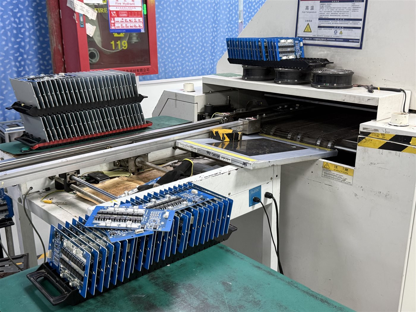
Inspection after placement and soldering should focus on the features that are visible at that stage: component identity and orientation, solder joints that can be seen, and connector seating. IPC distinguishes soldering process requirements in J-STD-001 from post-assembly acceptability in IPC-A-610; specify the applicable revisions and class in the purchase package rather than treating either document as a complete functional test plan. See IPC’s description of the J revisions.
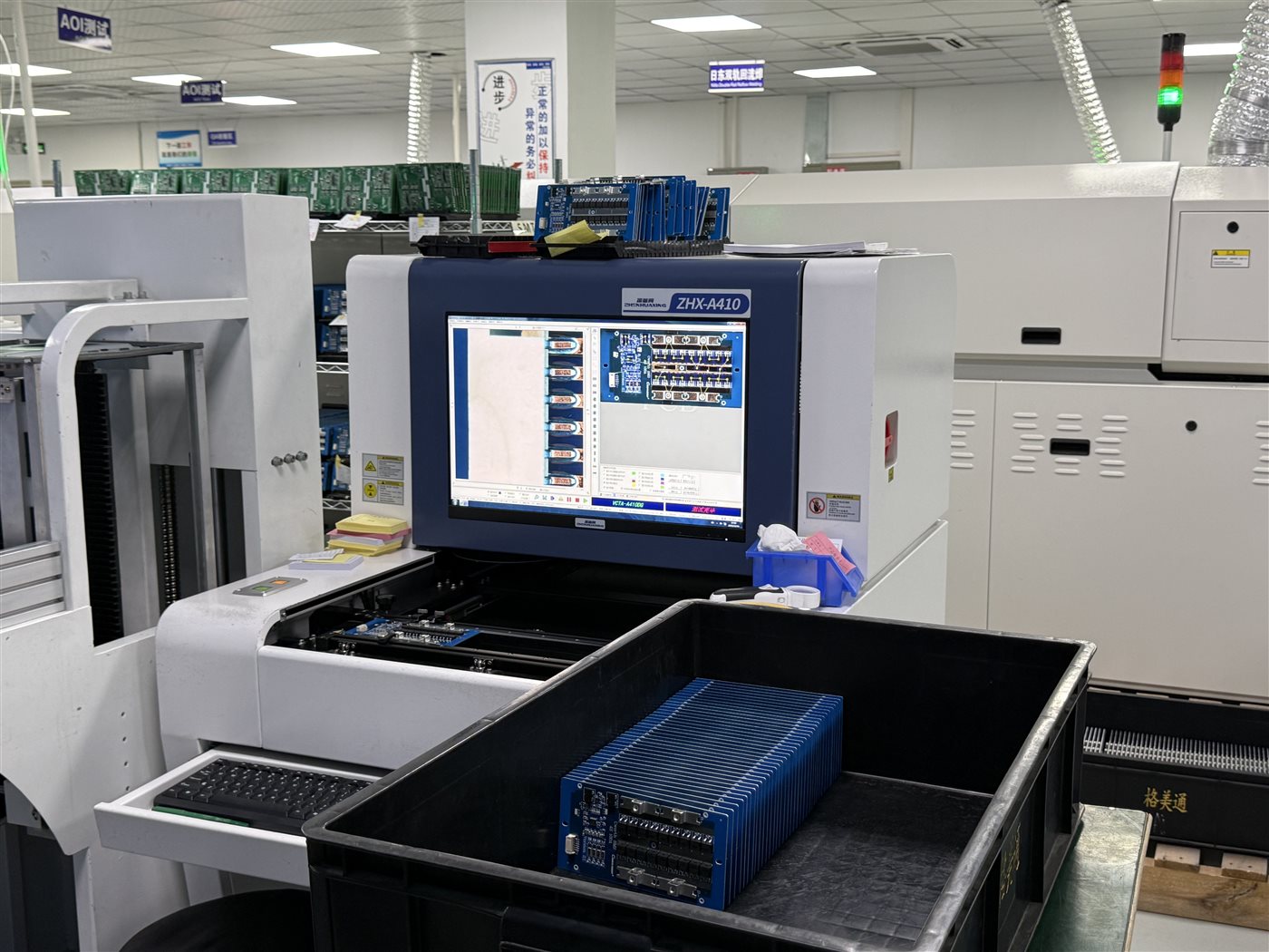
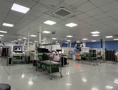
The verified OrinewPCB AOI factory demonstration shows an optical-inspection step. AOI can flag visible assembly conditions, but it cannot prove firmware behavior, loaded outputs, or cap application performance.
Keep inspection evidence tied to the actual assembly revision. If a through-hole part is installed after an earlier optical pass, the later solder joints still need their agreed inspection. The inspection traveler should identify when a defect was found, the approved repair, and whether the repaired unit returns to the same or an additional test gate. This prevents a passed machine report from masking an unrecorded board rework.
Make test access a release gate before coating
Before committing the coating keepout drawing, locate programming pads, test points, connector mating surfaces, adjustable devices, labels, and heat-transfer interfaces. The design owner should approve which remain uncoated and accessible. A fixture plan should describe power rails, firmware identification, input stimulation, output loading, communication, and fault responses where those functions exist. It should also name the machine functions that cannot be accepted on a board fixture.
Define the test fixture’s limits in engineering units and the method used to reach each signal. For example, a digital sensor input can be exercised at its connector while an output is checked under an approved representative load. If the controller includes an analog torque or force input, the OEM must specify stimulus accuracy and acceptance limits; a simulated value cannot demonstrate cap torque on the complete machine. Record the firmware checksum or other approved identifier alongside the board serial number so an apparently identical board cannot pass with the wrong program.
For a project with several boards or suppliers, share the controlled BOM, assembly files, test access map, and coating requirements for manufacturing review. The response can then separate fabrication, sourcing, assembly, programming, and test scope before prices are compared.
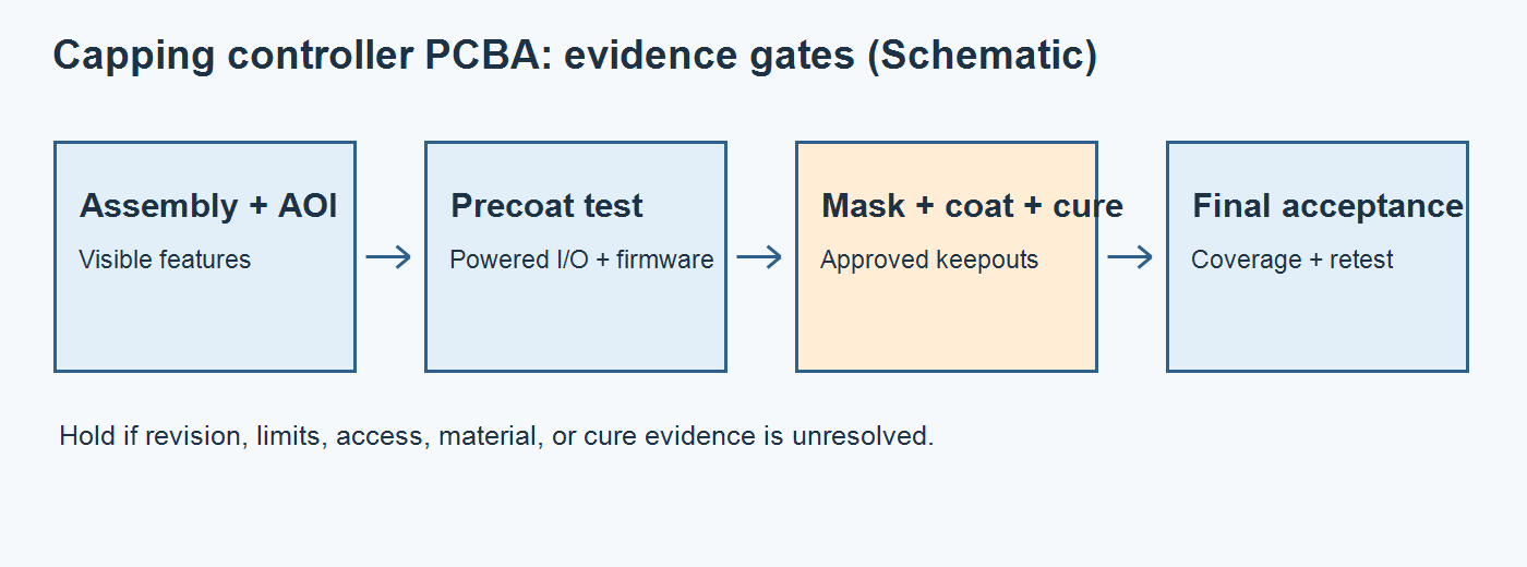
The table turns each handoff into a release decision. Its evidence column is a procurement request, not a claim that every capping controller uses the same fixture or coating chemistry.
| Gate | Decision before proceeding | Record to request | Hold if missing |
|---|---|---|---|
| Design input | Board, BOM, firmware, and variant agree | Revision-controlled build pack and approved alternates | Any unresolved part or pinout change |
| Assembly and inspection | SMT and through-hole routes fit part constraints; visible defects addressed | Traveler, inspection criteria, rework disposition | Unapproved solder method or open defect |
| Precoat functional test | Required board-level I/O and programming are accessible and pass limits | Fixture revision, firmware ID, unit result, limit set | Failed or untested required function |
| Coating release | Mask/keepout map, material, preparation, application, and cure are approved | Process instruction and material/cure record | Unresolved connector or test-pad coverage |
| Final acceptance | Coating coverage and any required postcure electrical checks pass | Visual record, traceable retest, exception disposition | Coating defect or lost test access |
Define coating keepouts and the retest boundary
Coating is a design and process choice, not an automatic requirement for packaging equipment. Ask what exposure the assembled controller actually faces, which surfaces need protection, and whether cleaning and dryness are required for the selected material. The MG Chemicals application guide calls out surface preparation and masking of areas that should remain uncoated; the exact method and cure must follow the approved material specification. IPC-CC-830 addresses coating material qualification, while IPC-HDBK-830 discusses selection and application; neither substitutes for a board-specific keepout drawing.
Mask the contacts and access points named by design, verify the mask before application, then document cure against the material and process. Decide in advance whether the board needs only postcure visual inspection or an additional powered check. A high-reliability function may require retesting after masking removal; a particular unit’s method and limits belong in the agreed test plan. The coating-versus-potting comparison provides a useful boundary when serviceability and environmental protection compete, although the machine application differs.
Where an OEM plans field rework, ask how the coating can be removed and reapplied without disturbing nearby components. Include that operation in the change and repair instructions. Do not promise corrosion resistance or coating life from a material name alone; environment, coverage, cure, and validation determine the result.
Quote lead time from the actual critical path
Request dates for PCB fabrication, long-lead approved components, fixture design, assembly, programming, first-article review, coating preparation and cure, and final test. Some tasks overlap: fixture design can begin while parts are sourced, but a locked test limit set and access map may be prerequisites. The delivery estimate should follow the longest dependent chain plus any customer approval hold, not the sum of every line item or an unexplained standard turnaround.
Split prototype and repeat-production assumptions. The first lot may need fixture debugging and a customer disposition of first-article evidence; a repeat lot may reuse a proven fixture only if the board, firmware, and limits remain controlled. A coating change or new supplier can reopen qualification. Ask which milestones trigger a fresh sample build and which are handled through a documented equivalence review. That makes the schedule comparable across suppliers without promising a fixed number of days.
Ask each supplier to expose assumptions about buyer-supplied parts, alternate approvals, coating material availability, fixture ownership, yield or rework allowance, and whether test reports accompany the shipment. A full-service assembly provider can coordinate these steps, but the turnkey PCB assembly scope still needs a project-specific definition of test and coating deliverables. Comparing this scope prevents a short assembly quote from being mistaken for a finished, validated controller.
The final release package should pair each serial or lot identity with its board revision, BOM variant, firmware, precoat test result, coating traveler if applicable, and final acceptance disposition. Machine-level cap quality, torque, guarding, and safety validation remain with the equipment OEM. If the production decision is ready, provide the revision-controlled build pack and required acceptance records for a complete assembly quotation; engineering can review the sourcing, process, and test assumptions against the same scope.
Latest Blog

Contact Info
Phone: +86-755-82882936
Email: [email protected]
WhatsApp: +86-13570802455
Wechat: +86-13570802455
Address: 2nd floor,D Bldg.,Electric Link Technology Bldg.,Gongming,Guangming New Dist.,518106 Shenzhen, China