
Motor Capacitor Wiring Diagram: Start, Run, and Single-Phase Motor Connections

Table of Conent
Table of Conent
A motor capacitor wiring diagram shows how a capacitor connects to the main winding, auxiliary winding, and switching device in a single-phase motor circuit. The correct connection depends on the motor design. Permanent split capacitor (PSC), capacitor-start induction-run (CSIR), and capacitor-start capacitor-run (CSCR) motors do not use the same arrangement.
The safest engineering rule is simple: use the schematic printed on the motor, inside the terminal cover, or in the manufacturer’s documentation. Do not infer connections from wire color alone. The diagrams below explain functional relationships for design review and troubleshooting, not field instructions for an unidentified motor.
Safety note: Motor capacitors can retain a hazardous charge after power is removed, and many motor circuits operate directly from AC mains. Qualified personnel should isolate power, verify zero energy, discharge capacitors using an approved method, and follow applicable electrical rules before handling the circuit.
What a Motor Capacitor Does
A single-phase AC supply does not create a naturally rotating magnetic field at standstill. An auxiliary winding, placed at a different angle from the main winding, helps establish the phase displacement needed to start or operate the motor. A capacitor changes the current phase in that auxiliary branch.
The capacitor’s job depends on the motor topology:
- Start capacitor: provides a large phase shift and higher starting torque for a short period. A centrifugal switch, potential relay, current relay, electronic module, or controller removes it after acceleration.
- Run capacitor: remains connected during normal operation. It supports phase shift, efficiency, power factor, torque, and winding current balance.
- Start and run capacitors: a CSCR motor uses both. The run capacitor remains active while the start capacitor is switched in only during startup.
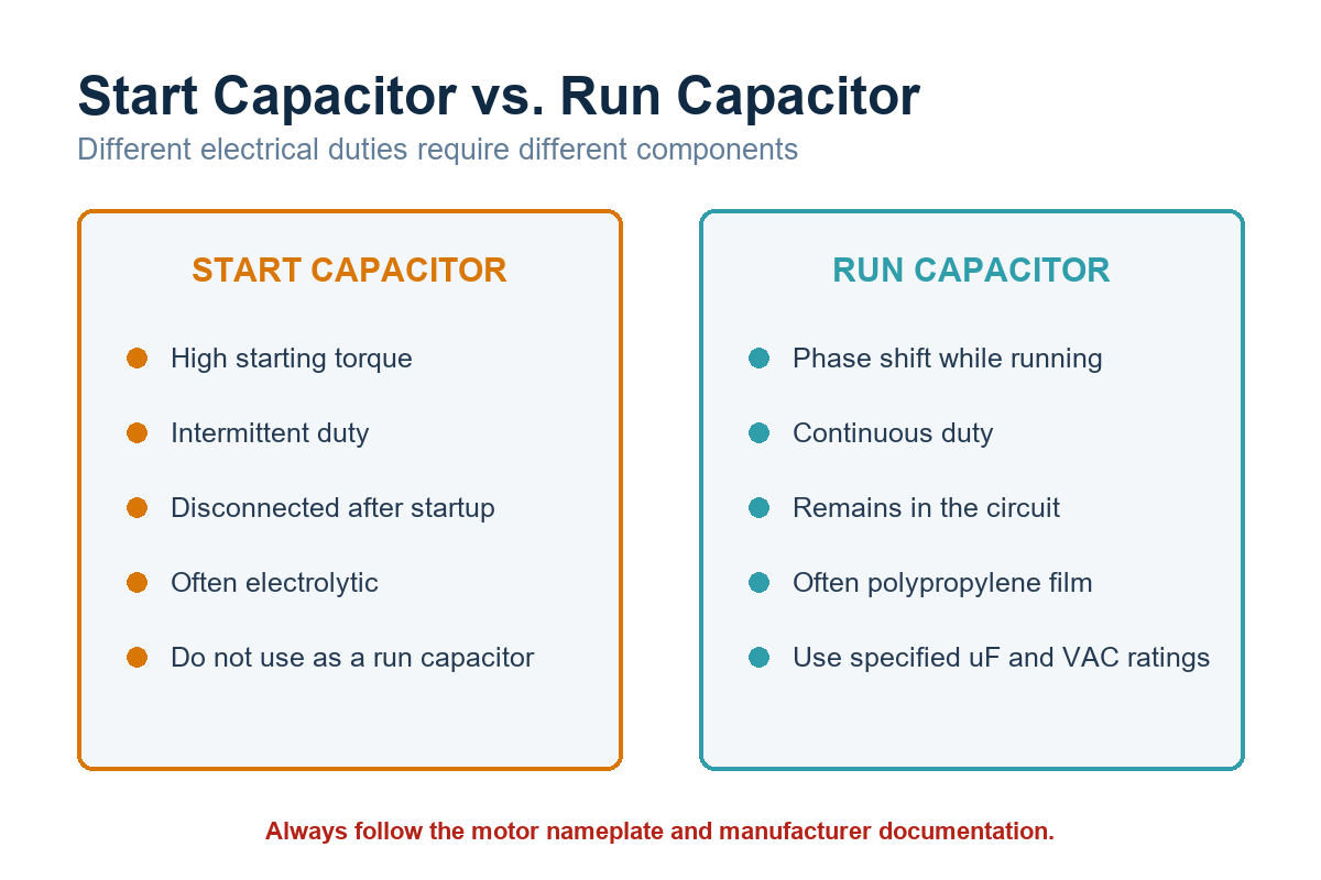
Start Capacitor vs. Run Capacitor
A start capacitor is commonly designed for intermittent duty. It may have a relatively high capacitance and is energized only long enough to bring the motor toward operating speed. Leaving it connected can cause overheating, swelling, venting, or winding damage.
A run capacitor is designed for continuous AC service. Metallized polypropylene film is common because it offers low loss and self-healing behavior. The marked voltage is an AC working rating, not a direct equivalent of a DC capacitor rating.
| Attribute | Start capacitor | Run capacitor |
|---|---|---|
| Primary function | Increase starting torque | Maintain phase shift during operation |
| Duty | Intermittent | Continuous |
| Typical construction | Motor-start electrolytic | Metallized film |
| Disconnection | Switch, relay, or electronic control | Normally remains connected |
| Selection basis | Motor specification and start time | Specified capacitance, VAC, tolerance, and temperature |
Never replace a run capacitor with a general-purpose electrolytic capacitor. Likewise, do not treat a start capacitor as a continuous-duty component. The motor manufacturer selects capacitance to match winding impedance and the desired torque-current relationship.
How to Read a Capacitor Start and Run Wiring Diagram
A capacitor start capacitor run wiring diagram usually contains four functional elements: the main winding, auxiliary winding, run capacitor, and start branch. The start branch may include a start capacitor plus a device that disconnects it after the motor accelerates.
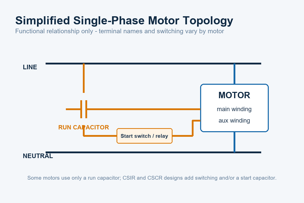
Many diagrams identify motor terminals as C, R, and S:
- C or Common: common connection shared by the winding branches.
- R or Run: terminal associated with the main or run winding.
- S or Start: terminal associated with the auxiliary or start winding.
These labels are common, not universal. HVAC dual-run capacitors may use C, FAN, and HERM, where HERM refers to the compressor branch. That convention should not be applied automatically to a bench motor, pump, blower, or custom machine.
PSC Motor
A permanent split capacitor motor normally keeps one run capacitor in series with the auxiliary winding. It has no separate start capacitor. PSC motors are common where moderate starting torque and quiet operation are more important than very high starting torque.
CSIR Motor
A capacitor-start induction-run motor places a start capacitor in the auxiliary branch during startup. After the motor reaches a defined speed or electrical condition, the start device opens and removes the capacitor and, depending on the design, the auxiliary winding.
CSCR Motor
A capacitor-start capacitor-run motor uses a run capacitor continuously and temporarily adds a start capacitor for higher starting torque. The start capacitor is commonly switched in parallel with the run capacitor during acceleration, but the exact circuit must be confirmed from the specified motor schematic.
Motor Start Capacitor Wiring Diagram Checks
Before interpreting or releasing a motor start capacitor wiring diagram, verify the following information:
- Motor nameplate: rated voltage, frequency, phase, full-load current, duty, and wiring designation.
- Manufacturer schematic: terminal labels, reversible connections, protector location, and start-device type.
- Capacitor data: capacitance in microfarads, tolerance, AC voltage rating, duty classification, frequency, temperature range, and safety approvals where required.
- Switching method: centrifugal switch, potential relay, current relay, PTC device, electronic start module, relay, triac, or external contactor.
- Protective devices: fuse, thermal protector, overload, surge protection, and enclosure grounding.
Wire colors may change between manufacturers, product revisions, harness suppliers, and repair history. A continuity or resistance measurement can support diagnosis, but it does not replace the approved connection diagram.
Selecting the Capacitor for a Motor-Control Assembly
Capacitance is only one line in the component specification. A production BOM should also control voltage rating, tolerance, operating temperature, lifetime or endurance class, mounting method, terminal style, enclosure, and applicable safety approvals.
Capacitance and Tolerance
An incorrect microfarad value changes auxiliary-winding current and phase angle. Too little capacitance may reduce starting torque or operating efficiency. Too much capacitance may increase current and winding temperature. Use the motor manufacturer’s specified value and tolerance rather than selecting a nearby catalog value without validation.
AC Voltage Rating
The capacitor voltage can differ from the line voltage because winding and capacitor voltages are vector quantities. Select the specified motor-run or motor-start AC rating with the required margin. Do not replace a motor capacitor based only on a higher-looking DC voltage printed on an unrelated component.
Duty and Temperature
Start duration, starts per hour, stalled-rotor conditions, ambient temperature, enclosure temperature, and airflow affect capacitor stress. A capacitor that works during a short bench test may still fail in a hot enclosure or a high-cycling application.
For guidance on interpreting small capacitor markings used elsewhere on a control board, see Capacitor Values 103: Design, Selection, and PCB Application Guide. Motor capacitors typically use explicit microfarad and AC voltage markings rather than the three-digit codes common on small ceramic components.
Connecting the Motor Circuit to a Control PCB
In many products, the high-energy capacitor and motor wiring sit outside the PCB while the board controls a relay, triac, solid-state relay, or contactor. The schematic and assembly documentation must show that boundary clearly.
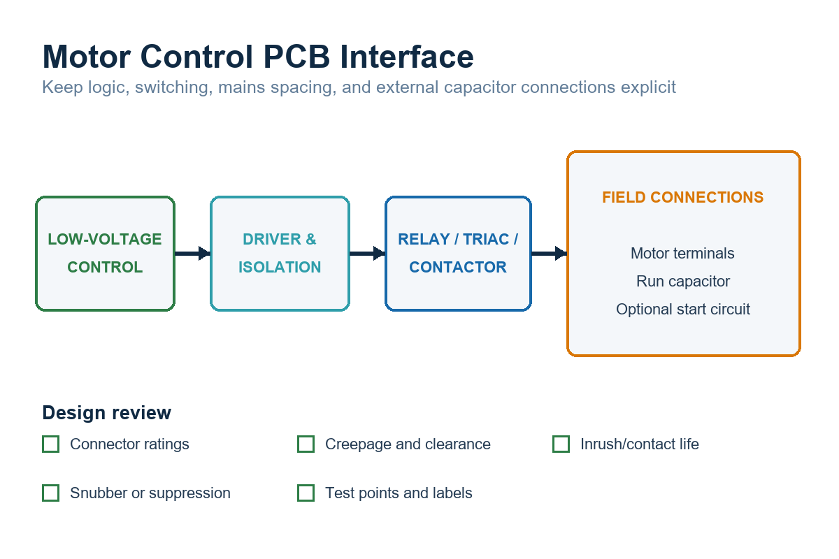
The control PCB review should cover:
- Switch ratings: motor loads have starting current, inductive interruption stress, contact arcing, and repetitive cycling. A relay’s resistive rating is not sufficient evidence for motor-load suitability.
- Creepage and clearance: spacing must reflect working voltage, transient category, pollution degree, material group, altitude, and the applicable product safety standard.
- Suppression: evaluate RC snubbers, MOVs, TVS devices, flyback paths, and EMI filtering based on the switching element and measured transient behavior.
- Connectors: verify current, voltage, temperature, pitch, keying, retention, touch safety, wire gauge, and agency recognition where applicable.
- Isolation: maintain the required boundary between SELV/control circuits and hazardous-voltage nets. Slots or barriers may be appropriate, but they must be documented and manufacturable.
- Thermal design: review copper temperature rise, relay heating, terminal heating, nearby electrolytic life, and enclosure airflow.
- Test access: provide safe production test points and a defined procedure for checking control signals without probing exposed mains nodes.
If your team is still translating system documentation into a PCB schematic, Reading Wiring Diagrams for PCB Design explains how functional wiring information differs from a PCB-ready circuit definition.
PCB Layout and Assembly Details That Prevent Wiring Errors
Good silkscreen and documentation reduce assembly and service errors. Mark connector reference designators, pin numbers, protective-earth points, motor terminals, and capacitor terminals consistently across the schematic, PCB, harness drawing, BOM, and test instruction.
Do not rely on a label such as “CAP” when two capacitor functions are possible. Use identifiers such as RUN CAP and START CAP where space permits, and include the approved schematic revision in the manufacturing package. Keyed connectors are preferable when a reversed connection could damage the motor or create a safety hazard.
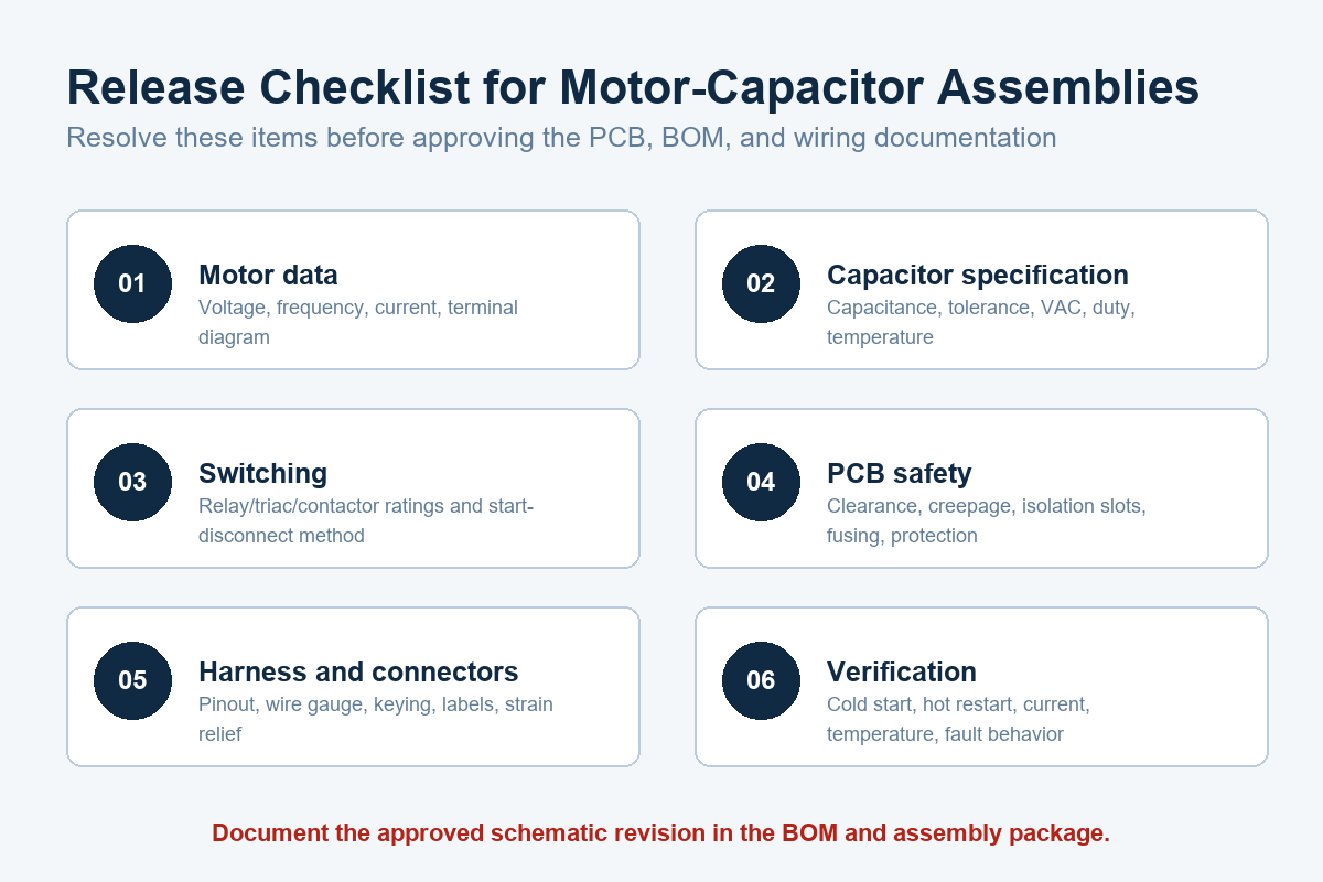
Preparing a motor-control PCB build? Submit the schematic, Gerber files, BOM, pick-and-place data, motor and capacitor specifications, harness drawing, target quantity, and test requirements through the PCB assembly quotation page. The package can then be reviewed for component sourcing, assembly requirements, and manufacturing risks before quotation.
Common Wiring and Design Mistakes
Using a Start Capacitor as a Run Capacitor
An intermittent-duty start capacitor may overheat rapidly when left energized. Match the capacitor type to its electrical duty, not just its capacitance.
Assuming C, R, and S Always Mean the Same Physical Pins
Terminal letters describe functions only when the manufacturer uses that convention. Confirm the terminal diagram and connector pin numbering for the exact motor part number.
Ignoring the Start-Disconnect Device
A failed potential relay, centrifugal switch, PTC device, or control relay can leave the start capacitor connected or prevent it from connecting. Replacing the capacitor alone may not correct the root cause.
Rating PCB Relays by Steady-State Current Only
Motor starting and interruption impose higher stress than a resistive load with the same running current. Review the relay or contactor data for motor, inductive, or horsepower ratings and validate the actual switching waveform.
Leaving Harness Decisions Until Production
Late connector or harness changes can alter creepage, current density, keying, test access, and enclosure fit. Treat the harness pinout as a controlled design input rather than an assembly detail.
Troubleshooting a Motor Capacitor Circuit
Symptoms can narrow the investigation, but they do not identify a failed component by themselves.
| Symptom | Possible causes to evaluate |
|---|---|
| Motor hums but does not start | Open or weak start capacitor, failed start switch/relay, mechanical load, low voltage, damaged auxiliary winding |
| Slow acceleration | Incorrect capacitance, excessive load, voltage drop, switching fault, winding damage |
| Start capacitor repeatedly fails | Excessive start time, too many starts per hour, failed disconnect device, incorrect voltage/duty rating |
| Motor runs hot | Incorrect run capacitance, supply problem, overload, ventilation issue, winding imbalance |
| Relay contacts fail early | Inrush, inductive arcing, inadequate motor-load rating, poor suppression, excessive cycling |
A disciplined diagnosis records supply voltage, start time, running current, capacitor value, capacitor voltage rating, switch behavior, winding resistance, load condition, and temperature. Replace parts only after comparing measurements with manufacturer limits.
Frequently Asked Questions
Does it matter which way a motor run capacitor is connected?
Most AC motor-run film capacitors are nonpolarized, so their two electrical terminals do not have positive and negative polarity. Multi-section capacitors and capacitors with labeled common terminals must still be connected according to their terminal markings.
Can I use a capacitor with a higher voltage rating?
A higher AC voltage rating is often electrically acceptable if capacitance, tolerance, duty, frequency, temperature, safety approvals, size, and mounting remain suitable. Confirm the substitution against the motor and product requirements.
Can a single-phase motor run without a capacitor?
It depends on the motor design. Shaded-pole and split-phase motors may not use a run capacitor, while PSC and CSCR motors require the specified capacitor arrangement. Do not bypass a capacitor in a motor designed to use one.
Why does a start capacitor fail after the motor starts?
A common cause is failure of the device intended to disconnect the start capacitor. Excessive start time, rapid cycling, incorrect capacitance, inadequate voltage rating, high temperature, or a mechanical overload can also contribute.
Final Design Review
A reliable motor capacitor wiring diagram begins with the exact motor specification, not a generic wire-color chart. Identify the motor topology, confirm every terminal, specify the capacitor’s complete electrical and mechanical requirements, and document the start-disconnect method. For PCB-controlled systems, review switching stress, spacing, protection, connectors, thermal behavior, and production test access as part of the same design.
When requesting a manufacturing review, provide the Gerber files, BOM, pick-and-place data, schematics, motor and capacitor datasheets, harness drawings, quantities, and test criteria. Request a PCB assembly quote with those files so the assembly scope and open engineering questions can be evaluated before production.
Latest Blog

Contact Info
Phone: +86-755-82882936
Email: [email protected]
WhatsApp: +86-13570802455
Wechat: +86-13570802455
Address: 2nd floor,D Bldg.,Electric Link Technology Bldg.,Gongming,Guangming New Dist.,518106 Shenzhen, China