
PCB Slots: Plated and Non-Plated Design and Release Checks
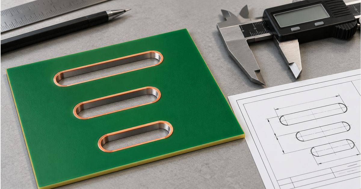
Table of Conent
Table of Conent
PCB slots accommodate features that do not fit a round hole, such as flat connector tabs, mechanical locating features, and selected board cut-outs. Their design involves more than drawing an oval. The fabricator needs to know which walls are plated, which dimensions describe the finished opening, where the slot belongs, and how the feature is represented in the release files.
A slot can look correct in a footprint preview and still arrive with the wrong width, orientation, or plating interpretation. The most effective prevention is a consistent definition across the component drawing, CAD object, drill or routing output, and fabrication notes. This guide explains the decisions that affect component fit and helps engineering and purchasing teams prepare an unambiguous order.
Choose plating from the feature’s function
A plated slot has conductive material on its internal wall. It may be part of a through-hole connection or a soldered mechanical tab, depending on the component design. A non-plated slot is a mechanical opening without intentionally plated walls. The appropriate choice comes from the component’s mounting requirements and the board’s intended electrical and mechanical function.
Do not assume that every connector mounting tab belongs on a ground net, or that every mechanical slot should be non-plated. Review the manufacturer’s recommended footprint, the tab’s function, and the assembly requirements. A shield tab, locating peg, and insulated mounting feature can require different treatments even when their outlines are similar.
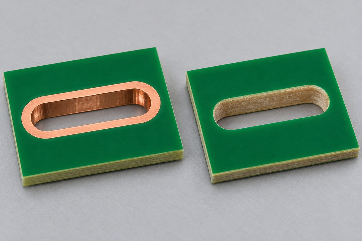
State the plating requirement explicitly. Copper around an opening is not a reliable substitute for a written plating designation. If a non-plated feature intersects copper intentionally, call attention to that exception and confirm how the fabricator will interpret it. Do not rely on an automated viewer to infer the engineering intent.
Define finished width, length, and orientation
For a common round-ended slot, identify its width, overall end-to-end length, angular orientation, and location relative to a documented datum. Make clear that the length includes the rounded ends. Tool travel or center-to-center length is a different quantity and should not be substituted without explanation.
For ideal semicircular ends, the end radius is half the slot width. If a mating feature requires another geometry, show that geometry rather than labeling every elongated opening a standard slot. A larger internal cut-out with multiple edges may need a closed contour and separately specified corner radii.
In a hypothetical example, an ideal slot with a finished width of 1.00 mm and overall length of 3.00 mm has semicircular ends of radius 0.50 mm. The straight portion between the end-center locations is 2.00 mm. These numbers illustrate the meaning of the dimensions; they are not a recommended footprint, fabrication limit, or order requirement.
Give the fabricator the finished requirements, including their tolerances. Let the production review determine the tooling and plating compensation needed to achieve them. Specifying both an assumed cutter and a conflicting finished opening can create an unnecessary ambiguity.
Evaluate component fit as a tolerance problem
Check more than the nominal tab width. Review the component drawing’s maximum tab dimensions, corner shape, position tolerance, and relevant lead or mounting-feature finish. Compare those with the board’s minimum finished opening and location requirements. The tab’s rectangular corners also need to fit within the rounded slot envelope, not merely within its total length.
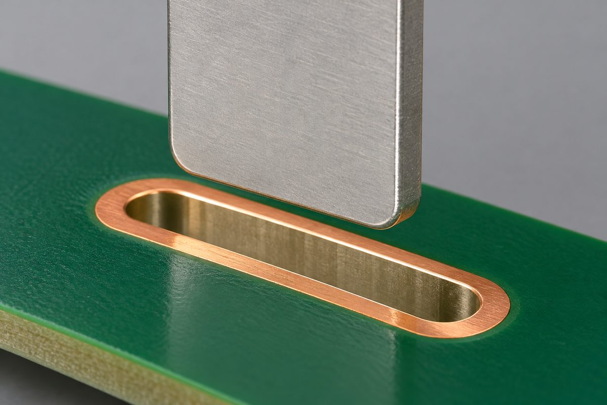
For an idealized example, a tab with a maximum thickness of 0.80 mm and a slot with a minimum finished width of 1.00 mm leave 0.20 mm total width difference. That is not automatically 0.10 mm usable clearance on each side: the tab may be off-center, and other positional or shape effects remain. Treat this as a first comparison, not proof that the assembly will fit.
Multiple tabs on one connector make positional relationships especially important. A single tab may enter its slot while another binds because the combined slot pattern and component geometry do not align. Review the complete footprint against the same datum system, rather than checking each slot independently.
For a connector with uncertain fit requirements, submit the component drawing, proposed slot dimensions, and finished tolerances for an engineering and quotation review. Identify which dimensions are critical so any proposed fabrication change can be assessed before release.
Account for the plated opening, not just the cutter
The production opening for a plated slot is not necessarily the same size as the finished opening. Material added to the walls changes the space available for the component. Eurocircuits’ finished-slot tolerance guidance describes contributions from tooling, cleaning, plating, and surface finish.
That supplier’s tooling increments and process values are not AssyPCB specifications. Confirm the actual order requirements and manufacturing assumptions for your board. Avoid adding a fixed plating allowance from an unrelated website to every slot in a library.
For a plated feature, review the surrounding copper land on relevant layers as well as the opening. Position variation can reduce the copper margin at one side or rounded end. Our annular-ring design guide explains why nominal geometry and the minimum remaining copper are different questions. A circular-hole calculation is not a complete assessment of an elongated land with different clearances around its perimeter.
For a non-plated feature, check the agreed copper clearance around the routed opening, including internal layers where applicable. Use the fabricator’s confirmed rules for the construction. Increasing the slot size to improve fit may also reduce nearby copper clearance or leave a narrower board section.
Use an actual slot definition in CAD
Where the design tool supports slotted through-hole pads, use the appropriate object and verify its plating setting. Keep the copper land shape separate from the hole shape: an oval copper pad around a round hole is not a slotted opening.
Altium’s pad and via documentation identifies a round-ended slot hole type and separate controls for its size, length, and rotation. The practical lesson is to inspect the hole attributes themselves, not only the copper outline displayed in the editor.
Do not simulate a slot as a chain of overlapping drilled holes unless the fabricator has explicitly accepted that representation and manufacturing approach. It can communicate a different feature and leave the intended smooth boundary unclear. A recognized slot definition or agreed routing contour gives the production reviewer a more explicit starting point.
After editing the library, update the placed footprint deliberately and rerun relevant design checks. Inspect the actual board instance to ensure that an older footprint version has not retained a different hole or plating attribute.
Make the release files agree
The drill or routing data and the mechanical drawing should describe the same feature. Eurocircuits’ slots and cut-outs guidance illustrates how incomplete slot definitions and unclear file assignments can require clarification. File naming and notes should tell the recipient where the authoritative geometry is located.
Agree on the accepted output format with the fabricator. If slots are supplied in a drill file, confirm that the chosen slot representation is supported. If supplied as routing contours, specify the file and distinguish the physical boundary from a tool-center path. Avoid providing two conflicting geometries with no indication of precedence.
Open the exported package in an independent viewer. Check that the slots appear at the intended coordinates and rotation relative to the board outline and copper. Verify units and origin, and ensure the plated and non-plated features remain distinguishable after export.
The PCB design manufacturing-file checklist provides a broader release context. A clean on-screen layout is useful, but the exported files are what the production team receives.
If an output viewer renders a slot unexpectedly, send the exported package, a marked drawing, and the intended plating designations for a file interpretation review. Resolve the discrepancy before approving tooling rather than assuming the preview is merely cosmetic.
Review practical fabrication and assembly tradeoffs
A narrow slot, tightly controlled fit, or dense slot pattern may require additional review. Ask whether the selected dimensions and tolerances are compatible with the board thickness and intended process. Do not assume that a minimum width offered for one construction applies unchanged to another.
Consider the board material remaining between nearby slots and the board edge. Also check assembly access around soldered tabs and any fixture support needed for the selected assembly method. A geometric fit solution should not obstruct soldering or create an unsupported narrow region during handling.
Use the PCB manufacturing capabilities page as a starting point, then confirm your slot construction and critical tolerances with the actual fabrication package. No generic capability table approves a specific connector footprint by itself.
Release and acceptance checklist
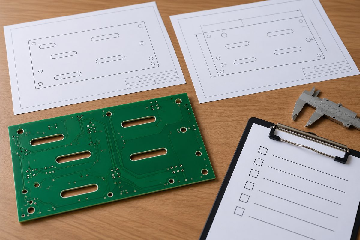
- Identify the component or mechanical feature that each slot supports.
- Specify plated or non-plated construction explicitly.
- State finished width, overall length, orientation, location, and relevant tolerances.
- Check the mating feature against the complete rounded opening and positional requirements.
- Review surrounding lands, clearances, and remaining board material.
- Verify slot representation, units, origin, and file revision in the exported package.
- Agree on inspection evidence for critical dimensions before ordering.
For incoming acceptance, separate dimensional evidence from electrical continuity and assembly fit. A continuity result does not measure slot width, and a single successful insertion does not document every tolerance. Record the inspected feature, board revision, measurement basis, and applicable requirement.
Preparing an order? send the fabrication files, connector drawing, quantities, and critical slot inspection requirements for review and quotation. A clear finished-feature definition lets engineering and purchasing discuss the same requirement, reducing the chance that a correct-looking drawing becomes the wrong manufactured opening.
Latest Blog


Contact Info
Phone: +86-755-82882936
Email: [email protected]
WhatsApp: +86-13570802455
Wechat: +86-13570802455
Address: 2nd floor,D Bldg.,Electric Link Technology Bldg.,Gongming,Guangming New Dist.,518106 Shenzhen, China