
Excellon Drill Files: Units, Tool Tables, and Release Checks
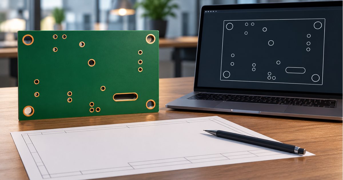
Table of Conent
Table of Conent
Excellon drill files communicate PCB hole locations and sizes to a fabricator’s CAM workflow. They belong in the fabrication package alongside copper artwork, the board outline, and construction requirements. A drill file is not simply a picture of holes, and a readable file is not necessarily an unambiguous one.
The main release risks are interpretation errors: incorrect units, an assumed coordinate format, a mismatched origin, incomplete tool definitions, or unclear plated and non-plated features. This guide focuses on checking those inputs before ordering. It does not provide a machine-ready drilling program or prescribe one export setting for every CAD tool and fabrication process.
Understand what the file does and does not specify
An NC drill file generally associates hole features with size definitions and coordinates. Depending on the export dialect, it can also carry information used to describe routed features. The receiving system must interpret the file’s units, numerical representation, and feature definitions correctly.
The filename extension alone does not establish the complete format. Two files named with the same extension can use different header conventions or slot representations. Confirm the accepted output with the supplier, particularly when changing CAD versions or reusing an old export preset.
Ucamco’s XNC specification defines a constrained CAD-to-CAM exchange subset associated with Excellon/IPC-NC-349. It also distinguishes exchange data from the fabrication equipment’s final instructions. The fabricator can process the supplied design data before generating the program required by its equipment; a CAD export should not be treated as a universal direct-to-machine program.
The drill file does not replace requirements such as stackup, finished-hole tolerances, or critical fit notes. Keep those in the agreed fabrication documentation and identify how they relate to the supplied hole data.
Make units and coordinate interpretation explicit
Confirm whether coordinates and size definitions use millimeters or inches. Then check how the export represents numbers: explicit decimal points or fixed-point values with an implied decimal location. For a fixed-point representation, the integer and fractional digit convention is part of the interpretation.
Zero suppression introduces another setting. Leading or trailing zeros may be omitted from numerical fields, but the receiving system still needs the correct convention to reconstruct the intended value. Do not infer that convention from the apparent length of one coordinate or a familiar filename.
Altium’s fabrication-output documentation describes units, numerical formats, zero suppression, and origin settings for NC drill output. Its available choices demonstrate why export configuration and import interpretation must agree. They are not a reason to copy a setting from an unrelated project without checking the result.
As a hypothetical interpretation example, the integer-looking token 12345 would represent 12.345 units if three fractional digits were assumed, but 1.2345 units if four were assumed. This is not a complete Excellon record or an instruction to hand-edit one. It simply shows why an omitted decimal convention can change geometry even when every digit is preserved.
After export, measure a known spacing in the independent viewer. Choose a dimension documented in the design, not a visually estimated pad pitch. A recognizable pattern can still be displayed at the wrong scale.
Check the origin, orientation, and copper alignment
Drill data and copper artwork must describe the same board in the same coordinate system. An origin mismatch can move all holes while preserving their internal spacing. An unintended mirror can make the board pattern look plausible but reverse its relationship to the copper.
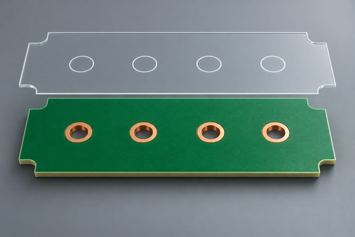
Load the exported drill data with the exported copper and outline, rather than reviewing the drill file in isolation. Inspect an asymmetric area, such as a connector pattern close to one corner. Symmetric patterns can conceal orientation mistakes.
If every feature is shifted by the same amount, investigate the origin before changing individual coordinates. If spacing is uniformly enlarged or reduced, investigate units or numerical interpretation. If only one feature family differs, inspect the relevant tool and export definition. These are diagnostic starting points, not conclusive causes.
For a disputed import, submit the fabrication package, export settings, and a marked reference dimension for a file interpretation review. Preserve the original files so the reviewer can distinguish an export problem from a viewer configuration problem.
Audit the tool table against the intended hole sizes
A size table and its identifiers connect features to the intended opening sizes. Check that every used identifier has a definition and that the associated diameter is interpreted in the correct units. Compare a representative hole from each family with the design’s hole summary.
Do not equate a label called “tool” in CAD exchange data with the physical drill bit selected on the production floor. Ucamco’s XNC definition explicitly describes its tool diameter as the finished size, with fabrication compensation handled separately. For other export workflows, confirm the dimensional meaning with the fabricator instead of making a universal assumption.
That distinction is especially important for component holes with fit tolerances. Do not add a guessed plating allowance to the exchange file merely because the eventual drilling operation uses a different production diameter. State the intended finished requirement and resolve how the supplier will interpret the exported values.
When comparing counts, compare like with like. Circular drill hits, routed slots, and different layer-pair outputs are not necessarily summarized as the same kind of event. A tool count that differs from a total feature count may be explainable; document the definition before concluding that holes are missing.
Keep plated status and hole span unambiguous
Distinguish plated holes from non-plated mechanical holes in the agreed output structure and documentation. Do not rely solely on copper around the opening to communicate plating intent. A mechanical opening can have special nearby copper geometry that makes automatic inference unreliable.
KiCad’s PCB Editor documentation describes separate plated and non-plated Excellon files by default, along with optional merged output. It recommends changing certain export options only when requested by the manufacturer. Keep the complete header and agreed file separation unless a verified receiving workflow requires otherwise.
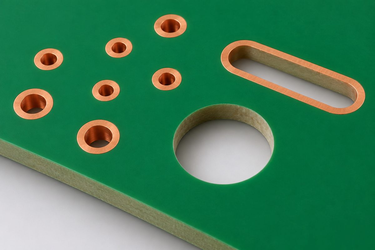
For blind or buried holes, identify the intended layer span and associate each output with the construction documentation. A coordinate list by itself does not necessarily describe the full drilling sequence. Ask how the supplier expects those files to be named and mapped.
Maintain a simple file manifest listing the filename, purpose, plating designation, and layer pair where relevant. Avoid renaming files in a way that removes useful export information or creates two apparently authoritative versions.
Treat slots as features, not decorative artwork
A slot drawn only on a reference drawing can be overlooked if the authoritative fabrication data does not define it. Conversely, a slot representation in the drill output may require an import mode supported by the receiving CAM system.
Confirm the accepted slot representation and compare its rendered width, overall length, position, and orientation with the mechanical requirements. Do not switch an oval-hole export option simply because another manufacturer’s guide used it. The correct choice depends on the actual recipient.
Our plated and non-plated slot design guide explains the distinction between finished dimensions, copper lands, and connector fit. A correctly located slot can still have the wrong dimensional or plating interpretation.
If slots appear as circles, disappear, or render differently between viewers, send the drill output, slot drawing, and intended finished dimensions for a manufacturing-data review. Ask for clarification before changing the design to match an unexplained preview.
Review the complete release package
A drill map is a useful visual companion, but it should not substitute for the machine-readable exchange data. Include the agreed files and confirm that the map, hole table, copper, and drawing refer to the same revision.
The CAD manufacturing-file checklist provides a broader review context. Check the actual exported package, not just the editor’s current board, because an older file can remain in the output folder after a new design change.
Use the PCB manufacturing capabilities page as a starting point for construction discussions. Confirm supported exchange settings and critical hole requirements with the submitted order data rather than assuming the page approves every output dialect.
A practical pre-order checklist
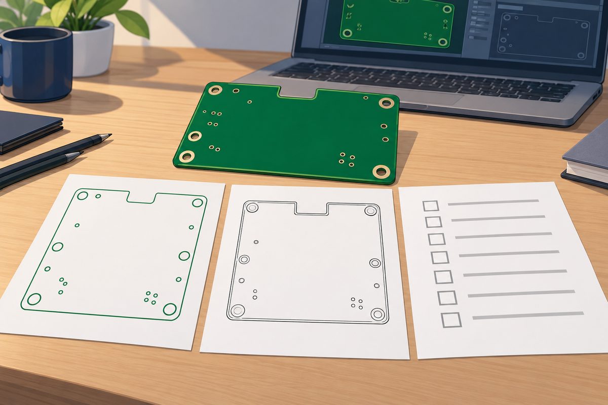
- Confirm the accepted NC exchange format and CAD export version.
- Verify units, decimal interpretation, and zero-suppression settings.
- Check a known dimension and an asymmetric reference feature.
- Overlay drills, copper, and outline using the intended origin.
- Compare tool definitions and representative holes with the design.
- Identify plated status, slots, and applicable layer pairs.
- Keep finished-hole requirements in the fabrication documentation.
- Remove ambiguity about which file revision is authoritative.
Keep a record of any interpretation agreed during the review. Re-export from the controlled design when a change is required, then repeat the checks on the new package rather than silently patching one coordinate file.
Preparing an order? send the final copper and drill files, stackup, quantities, and critical finished-hole requirements for review and quotation. Clear exchange data and consistent documentation give engineering and purchasing a shared basis for approval before fabrication begins.
Latest Blog

Contact Info
Phone: +86-755-82882936
Email: [email protected]
WhatsApp: +86-13570802455
Wechat: +86-13570802455
Address: 2nd floor,D Bldg.,Electric Link Technology Bldg.,Gongming,Guangming New Dist.,518106 Shenzhen, China