
Gerber X2: Layer Attributes and PCB Release Checks
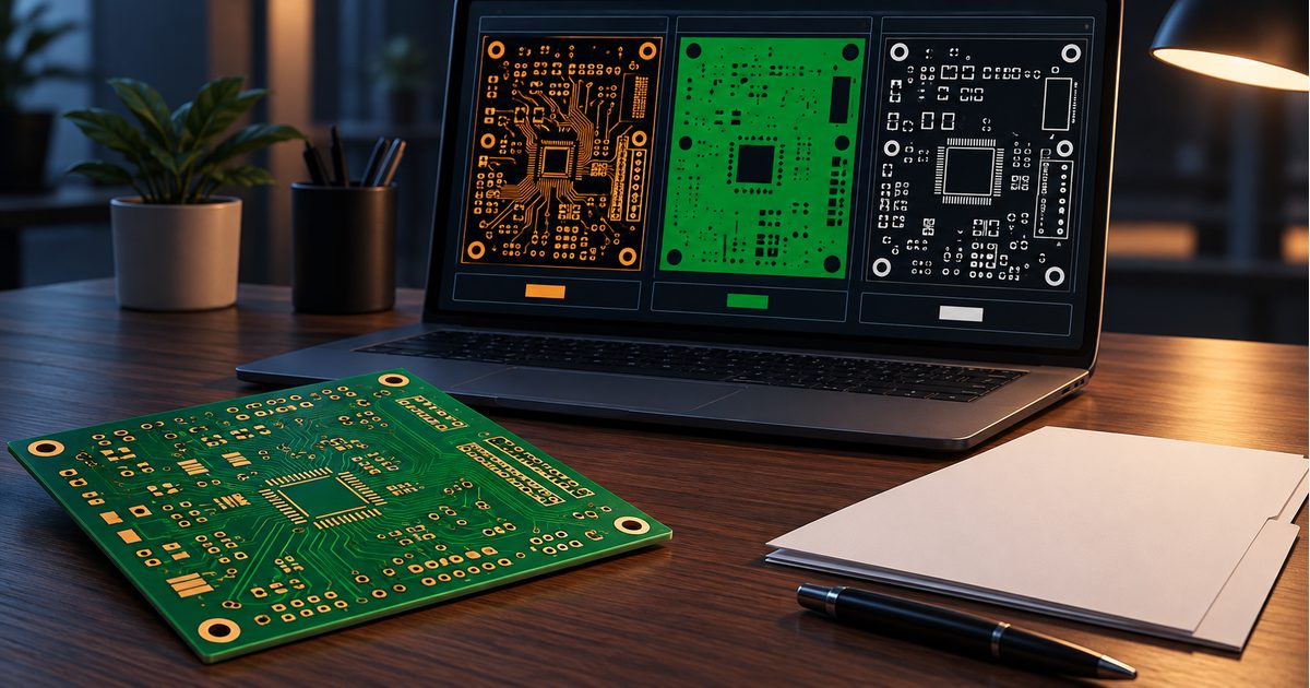
Table of Conent
Table of Conent
Gerber X2 adds standardized attributes to PCB fabrication artwork. Those attributes help communicate what a file or feature represents, rather than leaving the receiving team to infer its role from geometry and filenames alone. The benefit is clearer CAD-to-CAM communication, not a guarantee that a design is correct or that a fabrication package is complete.
For an engineering or purchasing team, the practical question is whether the exported files preserve both the intended images and the information needed to interpret them. This guide explains what to review, how to discuss compatibility with a fabricator, and how to keep the release package consistent without assuming that every viewer uses all available metadata.
Distinguish image geometry from attributes
The image describes the shapes on a fabrication layer. Attributes describe aspects of the file or its features. Ucamco’s official Gerber X2 overview gives examples including file function, polarity, part type, and pad function. A file can identify its role as copper or solder mask, while a feature can carry information about its intended function.
This distinction matters when two shapes look similar but serve different purposes. A circular feature might be a via-related pad or a fiducial. The geometry alone is not always enough to establish that role. Metadata can communicate intent, but it must agree with the underlying design.
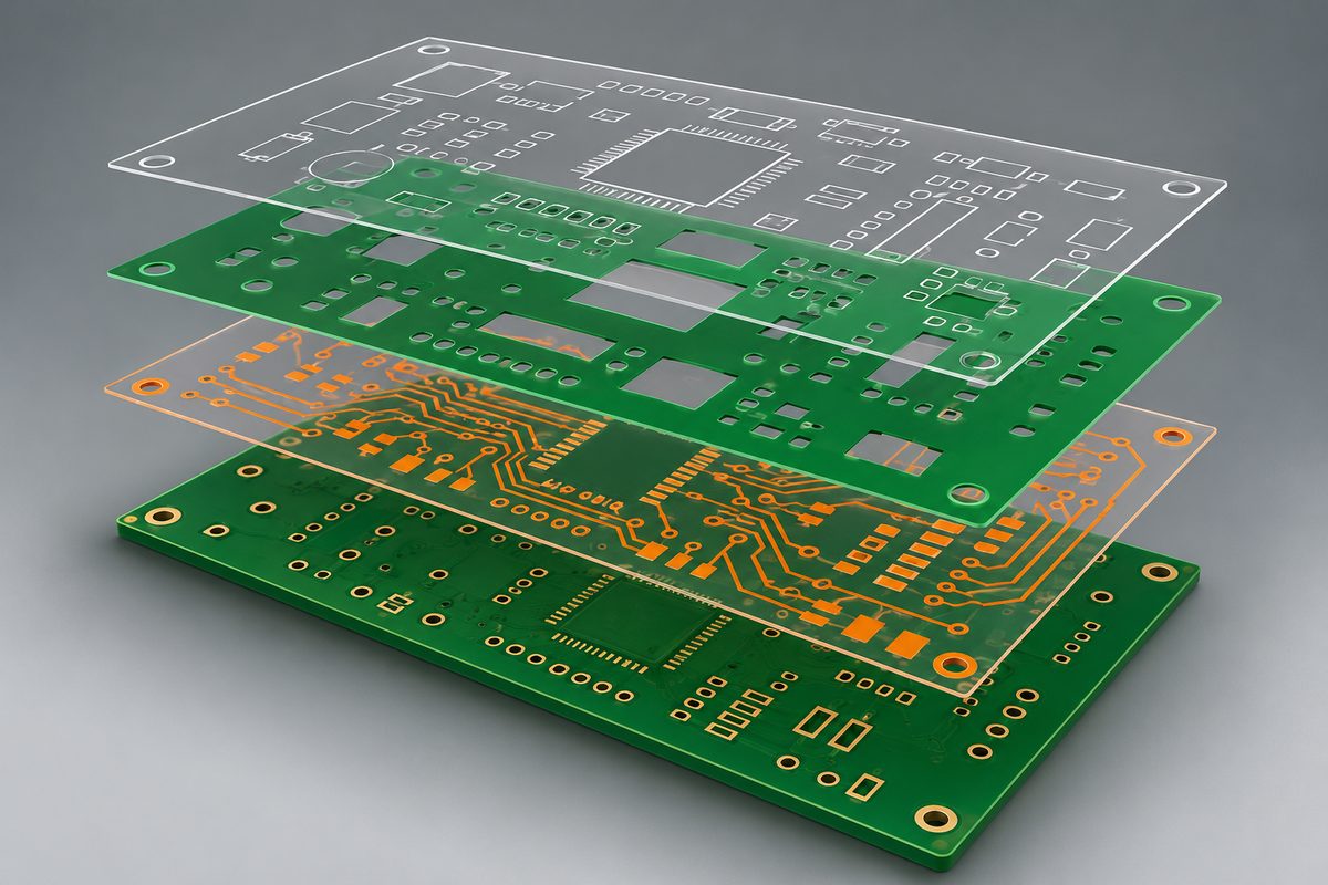
Do not confuse the identity of a copper layer with the complete physical construction of the board. A fabrication review still needs the agreed material, thickness, copper, and other order requirements. Treat attributes as useful structured information, not permission to omit construction documentation without confirming the receiving workflow.
Why a correct preview is only part of the review
A viewer can display an image without making practical use of every attribute. Ucamco explains that X2 attributes do not change image generation and that a compliant older Gerber reader can interpret the image while ignoring the attributes. That preserves geometry compatibility, but it does not mean the receiving software has used the metadata.
Ask two separate questions: does the receiving system render the artwork correctly, and does it use the attributes needed for the intended workflow? A supplier’s answer that it can “open the files” may address only the first question.
Conversely, do not remove metadata merely because a viewer displays an unfamiliar attribute warning. Determine whether the warning concerns unsupported information, an actual syntax problem, or a conflicting feature definition. A blanket instruction to ignore every warning would be just as unsafe as treating every warning as a failed design.
Preserve the original export while investigating an import problem. If the supplier requests a different output, regenerate that version from the controlled design and verify it independently. Avoid silently changing the archive that another reviewer has already approved.
Review layer identity against the intended board
Prepare a clear list of required fabrication layers and compare it with the exported files. Check top and bottom copper, internal copper where applicable, solder mask, legend, and the intended profile information. A file’s presence in the archive does not establish that it contains the correct layer.
Altium’s fabrication-data documentation describes selecting layers for Gerber and Gerber X2 output and configuring the generated file set. The important release habit is to verify those selections for the actual board rather than inheriting them unchanged from another project.
In a hypothetical example, a four-layer design could export four copper images while an old manifest lists a different internal-layer order. The images might all render cleanly, yet the package would still contain a conflict. Resolve the layer order in the design and documentation before placing the order.
Use filenames that remain understandable to people, even when attributes provide a machine-readable role. Do not rename one layer to mimic another or treat filename conventions as authority when the export metadata and drawing disagree. Document which released file set is authoritative.
If a layer assignment is uncertain, send the exported Gerber set, layer manifest, and stackup for a fabrication-data review. Identify the conflicting file or layer so the engineering discussion can resolve a specific interpretation before quotation or approval.
Check pad functions where they affect interpretation
Useful feature information should describe the design, not merely follow a convenient library default. Review representative surface-mount pads, vias, and fiducials in the exported package when the receiving viewer exposes their attributes.
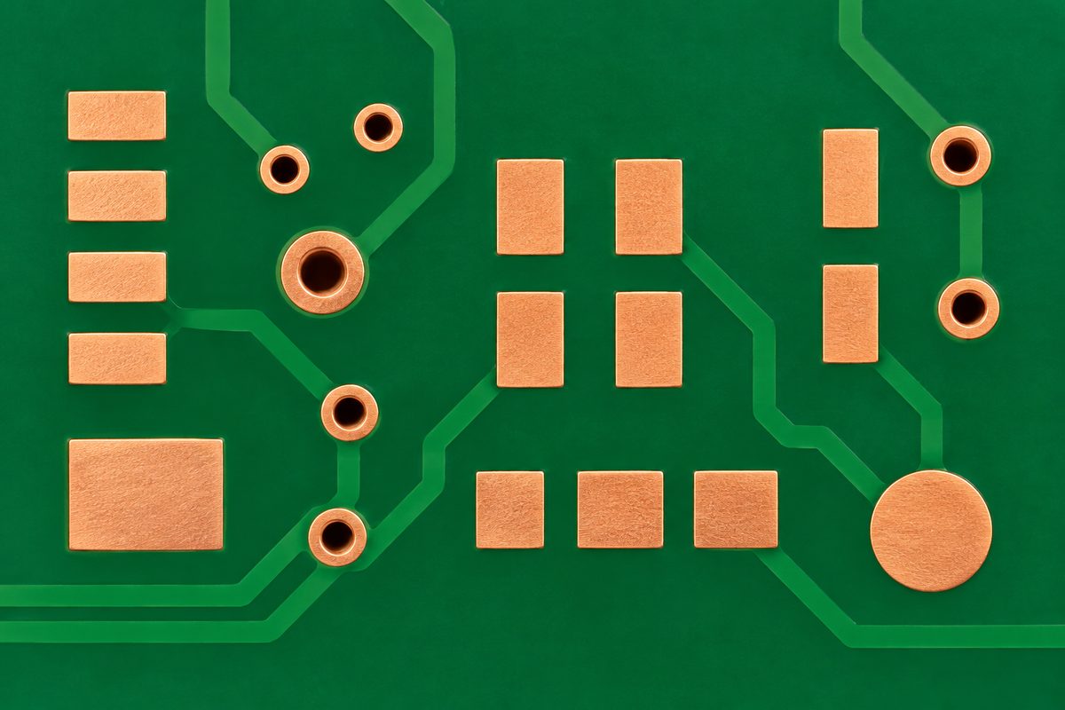
A visually similar shape can have a different intended purpose, so compare the exported role with the source object. If a custom footprint uses an unusual construction, explain it in the release notes rather than assuming a generic feature label captures every requirement.
Metadata should not be treated as automatic approval of solder mask, paste, or copper geometry. Inspect the images and the relevant design requirements separately. An accurately labeled pad can still have an unsuitable opening or clearance.
Do not hand-edit attributes to make a preview look more reassuring while leaving an incorrect source object unchanged. Correct the design or export configuration, regenerate the package, and repeat the review. That keeps later revisions from reintroducing the same inconsistency.
Keep drill data and the profile in the same coordinate system
Gerber X2 does not excuse a missing or misaligned hole-data package. Supply the agreed drill or routing representation and verify its relationship to copper and board geometry. Confirm that units, numerical interpretation, origin, and orientation produce the intended alignment.
Our Excellon drill-file release guide explains why a readable drill file can still be interpreted incorrectly. Layer attributes and drill interpretation solve related but different communication problems.
Inspect an asymmetric feature near a recognizable board corner. Uniformly spaced or symmetrical patterns can conceal a mirror or origin error. Check a known dimension as well as visual overlap; a scaled image can retain a familiar shape.
For slots or cut-outs, compare the exported representation with the finished-feature requirements. Identify where the authoritative geometry is located, particularly if the package contains both reference drawings and machine-readable feature data. Do not leave the supplier to choose between conflicting outlines.
Separate fabrication data from assembly requirements
A bare-board fabrication package and an assembly package serve different tasks. Copper artwork and layer attributes do not by themselves provide every component sourcing, placement, orientation, or testing requirement needed for an assembled product.
For an assembly order, include the agreed BOM, placement data, assembly drawings, and other project-specific inputs. Keep their revisions aligned with the board being manufactured. A correct Gerber archive paired with an older BOM can still describe the wrong build.
Ucamco’s CAD-to-CAM introduction to X2 frames attributes as structured image information. The release decision should remain tied to the actual work being ordered, not an assumption that choosing a modern format removes every supporting document.
If fabrication and assembly are being quoted together, submit the board files, BOM, placement data, quantities, and testing requirements for an engineering and quotation review. Clearly identify which documents belong to the same revision and which requirements still need confirmation.
Avoid mixed revisions and duplicate export sets
Export into a controlled release location and distinguish the final package from scratch outputs. If several versions remain in one archive, a reviewer may import an older layer or drill file despite the presence of newer data.
Use a manifest to associate filenames with their roles and revision. Include the relevant drawing and stackup references. An export date alone is not enough if two different board revisions were generated on the same day.
The CAD manufacturing-file checklist offers a broader framework for reviewing an exported package. Keep the review based on the actual files sent to the supplier, not an editor window that may have changed afterward.
If CAM review proposes a modification, record it and identify who approves the resulting change. Confirm whether the proposal affects artwork, dimensions, or only import interpretation. A request to rename a file is not equivalent to approval to change a footprint.
Confirm the receiving workflow before release
Use the PCB manufacturing capabilities page as a starting point for construction discussions, then confirm the accepted file format and required supporting documents with the actual order package. No generic capability listing certifies a particular export.
Ask for clarification where attributes, filenames, or drawings disagree. Do not accept an unexplained reinterpretation simply because the images look reasonable. A short discussion tied to a specific file is more useful than a general assurance that the format is supported.
Pre-order release checklist
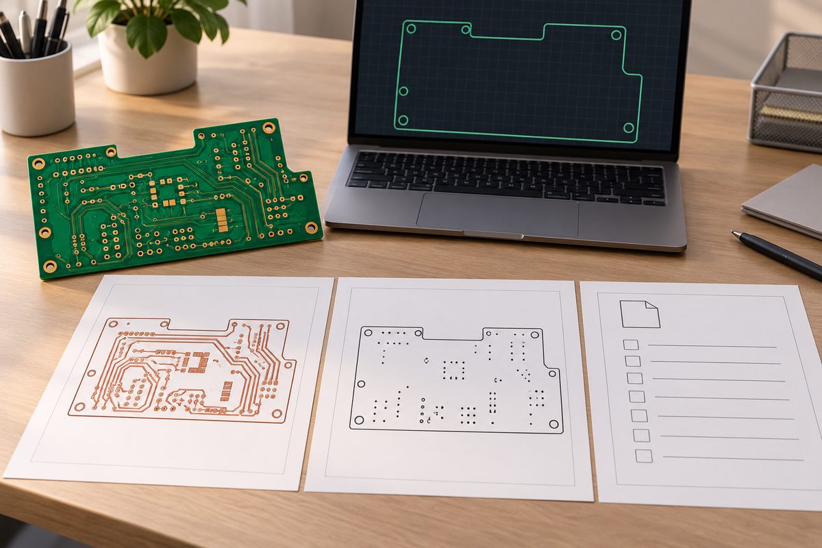
- Confirm the selected Gerber output and receiving workflow.
- Check required layers and their intended identities.
- Inspect representative feature roles where metadata is available.
- Review the rendered geometry independently of attribute labels.
- Align drill data, copper, and profile using the intended coordinates.
- Include the agreed stackup and finished-feature requirements.
- Remove ambiguity about duplicate files or mixed revisions.
- Document unresolved questions before production approval.
Ready to release? send the final Gerber and drill package, manifest, stackup, quantities, and critical requirements for review and quotation. Gerber X2 is most useful when its attributes, images, and supporting documents tell the same engineering story.
Latest Blog

Contact Info
Phone: +86-755-82882936
Email: [email protected]
WhatsApp: +86-13570802455
Wechat: +86-13570802455
Address: 2nd floor,D Bldg.,Electric Link Technology Bldg.,Gongming,Guangming New Dist.,518106 Shenzhen, China