
Digital Textile Printer PCBs: Select Laminate for Heat and Ink Exposure
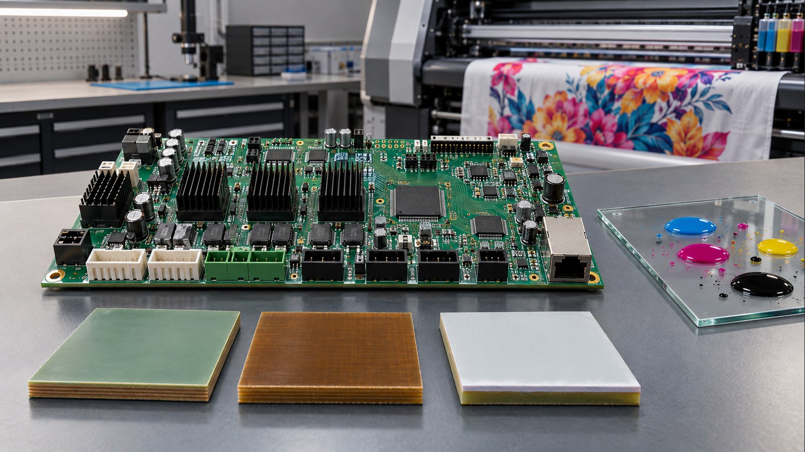
Table of Conent
Table of Conent
Digital Textile Printer PCBs: Select Laminate for Heat and Ink Exposure
A digital textile printer PCB should not be assigned a laminate from maximum ambient temperature alone. The correct choice depends on the board’s actual temperature profile, reflow cycles, copper density, voltage spacing, moisture exposure, cleaning chemistry, and the probability that ink or pretreatment fluid can reach the assembly. Start with a qualified material family that survives fabrication and assembly. Then control liquid exposure through enclosure design, drainage, connector selection, spacing, and—when justified—a compatible conformal coating. A high glass-transition temperature does not by itself make a bare PCB resistant to ink.
This distinction matters because thermal reliability and chemical protection are separate engineering problems. The laminate supports conductors and plated holes; the finished assembly still includes solder mask, exposed metal, component packages, connectors, labels, adhesives, and residues that may respond differently to heat, humidity, and fluids.
Define the printer environment before naming a laminate
The useful specification begins with zones and exposure paths. A controller mounted in a sealed electrical cabinet experiences a different environment from a carriage board near printheads, heaters, mist, and service cleaning. Record the local operating temperature, short-duration peaks, thermal cycling, humidity, condensation risk, airflow, and proximity to ink supply, purge, wash, and waste lines.
Identify the fluids by supplier and formulation rather than writing only “ink resistant.” Pigment, dye, reactive, acid, disperse, UV-curable, pretreatment, flushing, and cleaning fluids can contain different carriers and additives. Obtain safety and technical data where available, then define realistic contact: vapor, aerosol, droplets, splash, pooling, wipe cleaning, or prolonged immersion. Do not infer compatibility from color or water content.
The exposure map should include connectors, board edges, vias, test pads, switches, cooling openings, and cable entries. In many designs, relocating the assembly or adding a drip shield produces more reliable protection than selecting a specialty laminate while leaving exposed connectors in a splash path.
Use IPC-4101 slash sheets and supplier data, not “FR-4” alone
FR-4 describes a broad class, not a complete procurement specification. IPC states that IPC-4101 covers laminate and prepreg base materials for rigid and multilayer printed boards, with specification sheets defining material requirements. The current IPC revision table lists IPC-4101E with Amendment 1, while IPC-4101F remains under development as of this review. Call out the applicable slash sheet and the performance needed rather than relying on a generic trade name.
Confirm the revision when the drawing is released. IPC’s document revision table distinguishes current, historical, and superseded documents, which prevents a purchasing note from silently pointing to an obsolete material definition. If a customer specification fixes an older revision, record that requirement explicitly and resolve any conflict with the fabricator before ordering material.
Review at least glass-transition temperature (Tg), decomposition temperature (Td), time to delamination, coefficient of thermal expansion in the Z axis, moisture absorption, comparative tracking index where relevant, dielectric performance, flammability recognition, and conductive anodic filament resistance for the selected construction. IPC’s TM-650 test-method index includes methods for Td, bulk moisture, and CAF resistance, illustrating why these properties require defined tests rather than marketing adjectives.
Tg marks a change in polymer behavior; it is not a maximum continuous-use temperature. Td indicates a decomposition test condition, not an operating rating. Use the material supplier’s current datasheet and processing guidance together with the board fabricator’s qualified stackup.
Match thermal properties to assembly and service
High-Tg laminate may help when the PCB experiences repeated lead-free reflow, localized heater influence, high copper imbalance, or sustained cabinet temperature, but the complete thermal history controls the decision. Estimate junction and board temperatures for motor drivers, power supplies, heater controls, and printhead interfaces. Include reduced airflow from ink mist filters, dust, or enclosure restrictions.
Check copper distribution and stackup symmetry because a thermally capable resin system can still produce bow, twist, or assembly difficulty when the construction is unbalanced. Thermal cycling also stresses plated through-holes through Z-axis expansion. Define finished board thickness, copper weights, dielectric spacing, via structures, and reflow exposure with the fabricator before material approval.
If the printer has several electronics zones, do not force one premium material into every board without evidence. A carriage board, heater-control board, and remote HMI may justify different material or protection requirements. A controlled PCB assembly variant plan can keep those configurations and their BOM differences traceable.
Separate laminate selection from ink and cleaning-fluid protection
Ink compatibility must be evaluated at the assembly level. Liquid can travel along harnesses, under components, through unsealed connectors, or across contaminated surfaces. Even when the laminate resin tolerates brief contact, moisture and ionic residues can reduce insulation resistance or promote corrosion between biased conductors.
Use layered controls: prevent leaks, route fluid lines away from electronics, add drip paths and drainage, protect cable entries, select sealed connectors where needed, and maintain adequate creepage and clearance. Apply conformal coating only after defining keep-out areas, connector masking, coating thickness, cure, adhesion, inspection, rework, and compatibility with every relevant fluid. The decision framework in the conformal coating versus potting guide helps separate repairable surface protection from full encapsulation.
For a project-specific review, provide the stackup target, thermal map, fluid list, exposure duration, cleaning procedure, Gerbers, BOM, pick-and-place data, quantities, and coating keep-outs through the manufacturing package intake. That allows fabrication, material availability, assembly, masking, inspection, and verification requirements to be checked together.
Build a compatibility test around real failure modes
A generic material certificate cannot prove resistance to a proprietary ink system. Use representative production materials and an agreed test method. Include bare laminate coupons only to isolate material behavior; also test finished boards or assemblies because solder mask, finishes, components, connectors, labels, adhesives, and coatings may dominate the result.
- Condition samples at the specified temperature and humidity.
- Apply the relevant ink, pretreatment, flush, or cleaner by the expected contact method and duration.
- Include powered bias when electrochemical migration is a credible risk.
- Cycle temperature or repeat cleaning to represent service, not just a single splash.
- Inspect for swelling, discoloration, blistering, delamination, corrosion, residue, coating lift, and connector damage.
- Measure insulation resistance, leakage, functional behavior, and adhesion against predefined limits.
Document concentration, temperature, exposure time, rinse, dry time, electrical bias, sample construction, and pass/fail criteria. Without those conditions, “passed chemical test” cannot be reproduced or compared across suppliers.
Translate the decision into fabrication and assembly files
The fabrication drawing should state the laminate specification, applicable slash sheet, stackup, finished thickness, copper weight, surface finish, via requirements, and any material substitutions that require approval. The assembly drawing should identify coating material, coverage, keep-outs, masking, cure, thickness or acceptance method, and required inspection.
A structured PCB assembly drawing checklist reduces ambiguity around polarity, special processes, inspection, and test. For a one-stop build, align those documents with sourcing, SMT and through-hole assembly, cleaning, coating, programming, and functional test; the PCB assembly service overview shows the production stages that depend on a consistent release package.
Require lot traceability for the material identity agreed with the fabricator. If equivalent materials are permitted, define the minimum electrical, thermal, mechanical, flammability, and reliability properties rather than approving substitutes by Tg alone. Confirm that the chosen material is available in the required thicknesses, copper weights, and glass styles before freezing the stackup.
Release checklist for a digital textile printer PCB
- Board location, temperature profile, humidity, condensation, and fluid paths are documented.
- Ink, pretreatment, flush, and cleaning fluids are identified by current supplier data.
- Laminate selection includes Tg, Td, Z-axis expansion, moisture, CAF, dielectric, and flammability requirements as applicable.
- Enclosure, drainage, connector, spacing, and coating controls address liquid exposure separately.
- Compatibility tests use representative finished assemblies and defined conditions.
- Fabrication and assembly drawings state controlled requirements and substitution rules.
When these inputs are ready, send the released Gerbers, stackup, drawings, BOM, placement data, fluid list, coating requirements, quantities, and acceptance tests through the complete PCBA review package. Engineering and sourcing teams can then confirm the material, identify availability or process conflicts, and prepare a build and test scope tied to the printer’s real environment.
Conclusion
Digital textile printer PCB laminate selection works best when thermal durability and liquid protection are treated as separate but connected requirements. Specify a qualified laminate from the actual assembly and service temperatures, stackup, moisture, and electrical risks. Control ink exposure through mechanical design and, when justified, a validated coating system. Finally, test the finished assembly with the real fluids and operating conditions before releasing volume production.
Latest Blog

Contact Info
Phone: +86-755-82882936
Email: [email protected]
WhatsApp: +86-13570802455
Wechat: +86-13570802455
Address: 2nd floor,D Bldg.,Electric Link Technology Bldg.,Gongming,Guangming New Dist.,518106 Shenzhen, China