
Strapping Machine PCB Repair: When Rework Is Safe and When to Replace
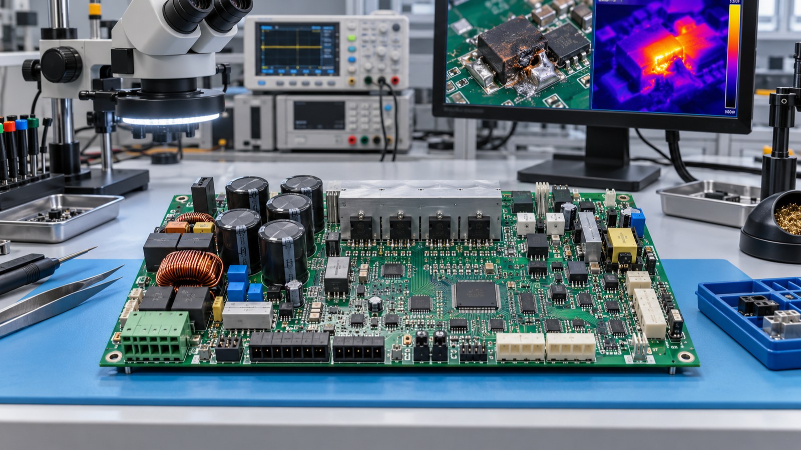
Table of Conent
Table of Conent
Strapping Machine PCB Repair: When Rework Is Safe and When to Replace
A strapping machine controller PCB is a sound rework candidate only when the failure is localized, the laminate and copper remain structurally stable, the root cause is understood, replacement parts are controlled, and the repaired assembly can be retested against defined machine functions. Replacement is the safer choice when heat or contamination has spread, pads or vias have lost integrity, safety-related circuits are uncertain, programmable parts cannot be restored, or repeated faults indicate a system-level problem. The decision should be based on evidence—not only whether a technician can make the board power up.
For packaging equipment, the controller often coordinates strap feed, tension, sealing, cutters, sensors, interlocks, and servo or motor outputs. A board that passes a bench power check can still fail under load or create unpredictable machine motion. The practical objective is therefore to restore a controlled, testable assembly with acceptable risk, while avoiding expensive replacement when a limited defect can be reworked without degrading the rest of the board.
Start with failure isolation, not component removal
The first decision is whether the defect belongs to the PCB at all. Verify the incoming supply, fuses, connectors, grounding, motor and solenoid loads, sensor signals, harness continuity, mechanical drag, and environmental conditions before applying heat to the board. A stalled motor, intermittent cable, contaminated photoelectric sensor, or loose terminal can overload a healthy controller and make a replacement board fail in the same way.
Capture symptoms under controlled conditions: operating mode, fault code, cycle step, load, temperature, and whether the fault is repeatable. Then compare power rails, reset behavior, communications, inputs, and outputs with the schematic or a known-good unit when one is legitimately available. Thermal imaging, current-limited power-up, oscilloscope measurements, and resistance checks can help narrow the fault, but each method needs appropriate limits and safe machine isolation.
This evidence-first approach is consistent with IPC’s overview of assembly, inspection, process-control, and acceptance standards: workmanship decisions depend on controlled requirements and evidence, not appearance alone. It also prevents a visually suspicious solder joint from becoming the default explanation for every intermittent problem.
Distinguish rework from repair before approving the job
Rework returns a nonconforming assembly to the applicable drawing or specification using the original or equivalent process. Repair restores function but may not return the assembly to full drawing compliance. That distinction affects authorization, documentation, acceptance criteria, and the evidence required before the controller goes back into service.
IPC lists IPC-7711/21D as the current revision of Rework, Modification and Repair of Electronic Assemblies, published in January 2024. The standard’s scope includes component removal and replacement as well as land, conductor, laminate, and coating procedures. IPC also treats training and technician skill as part of controlled rework: its 7711/7721 endorsement program covers tools, heating methods, handling, through-hole and surface-mount procedures, and board repair.
For an industrial controller, an authorized component replacement using the released part and documented process may be rework. A wire jumper across a damaged conductor, a replacement pad, or a reconstructed via is normally a repair and should be approved as such. If conformal coating must be removed and restored, define the keep-out area, cleaning method, cure condition, inspection, and final coverage; the same discipline used for conformal-coating control tools helps keep the restored area repeatable.
Use a repair-versus-replace decision framework
A safe decision combines defect extent, board condition, functional importance, process capability, and test coverage. No single visual clue is sufficient. Use the following framework as a gate before approving component removal or board-level reconstruction.
| Decision factor | Rework or limited repair may be reasonable | Replacement is usually safer |
|---|---|---|
| Defect extent | One identified component, joint, connector, or short conductor segment | Multiple unrelated faults, broad corrosion, or uncontrolled previous work |
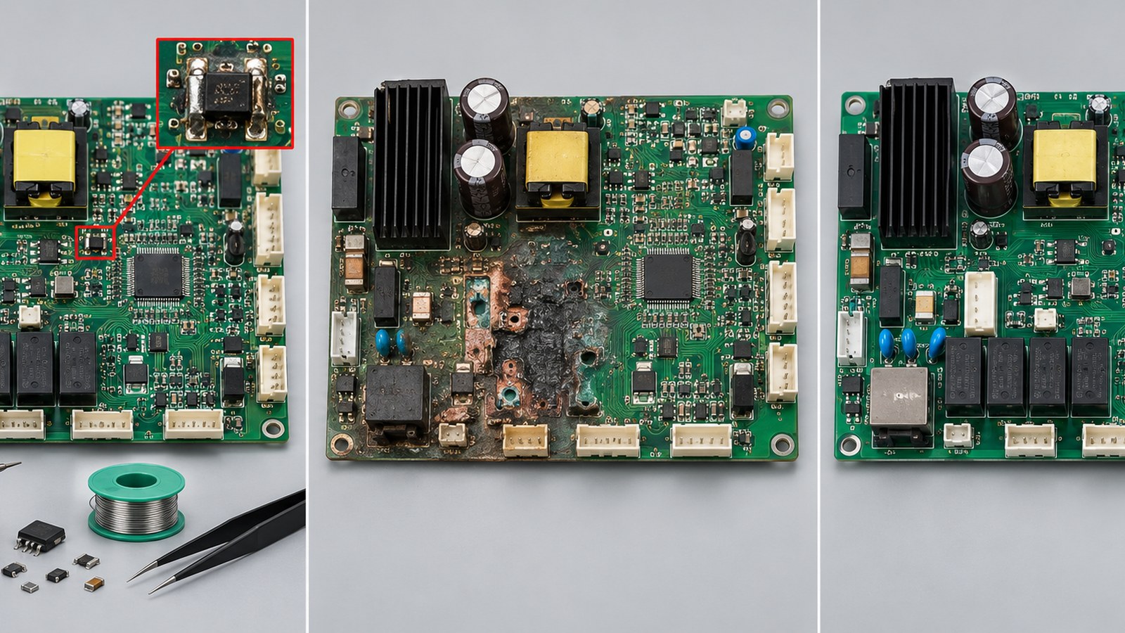
| Laminate and copper | No carbonization, stable pads and vias, no progressive delamination | Charred laminate, lifted pads across a dense area, cracked vias, or internal-layer uncertainty |
| Root cause | Confirmed component, joint, or connector failure with the external cause removed | Cause remains unknown or the machine repeatedly damages the same circuit |
| Parts and data | Traceable compatible parts, correct firmware, and controlled polarity or programming | Unknown substitute, locked programmable device, missing calibration data, or counterfeit risk |
| Testability | Critical inputs, outputs, interlocks, communications, and loaded cycles can be tested | Only power-on can be checked, or safety and high-energy functions cannot be verified |
Economics matter, but cost is not just the technician’s time. Include troubleshooting, fixtures, special tools, part traceability, process development, inspection, retest, documentation, expected remaining life, and production downtime. A low-cost repair with weak verification can be more expensive than replacement if the machine stops again during a shipment deadline.
If the board appears suitable for controlled work, share the failure evidence, Gerber or fabrication data when available, BOM, photos, machine I/O requirements, and test limits for a manufacturing review. That package lets fabrication, component sourcing, assembly, coating restoration, and functional-test assumptions be evaluated together before a repair route or replacement build is quoted.
Know which defects are poor candidates for repeated heat
Dense packages, heavy copper, heat-sunk power devices, aged laminate, and mixed lead-free/tin-lead history can make heat delivery difficult. Repeated local heating may lift pads, weaken barrels, warp the board, disturb nearby components, or leave flux residues under low-standoff packages. A repair plan should therefore specify preheat, nozzle or tip geometry, temperature measurement, shielding, dwell control, cleaning, and inspection rather than relying on operator feel.
A suspected BGA fault deserves particular caution. X-ray or electrical symptoms should first confirm the defect mechanism; for example, head-in-pillow diagnosis requires evidence at the interface before changing the process. Reballing or replacement does not correct board warpage, poor paste transfer, moisture, incompatible finishes, or a failing upstream power rail.
Power-stage damage also needs a boundary. A single gate resistor or driver may be replaceable when the MOSFETs, current sensing, isolation, DC bus, and motor load have been checked. Carbonized laminate around a high-energy fault is different: conductive residue and reduced insulation distance can persist even after a component is replaced. When structural or insulation integrity cannot be demonstrated, replacing the assembly avoids treating a functional power-up as proof of long-term safety.
Define acceptance tests before the iron heats up
The acceptance plan should be written before rework so the repaired board is not judged only by whether the original symptom disappeared. At minimum, inspection and testing should cover the affected circuit, adjacent heat-exposed areas, power rails, communication paths, relevant sensors and actuators, and the machine states that depend on them.
- Incoming inspection: record board identity, revision, firmware labels, prior repairs, contamination, connector condition, and the observed failure.
- Post-removal inspection: examine lands, mask, laminate, barrels, and nearby parts before installing a replacement.
- Workmanship inspection: apply the contractually selected criteria and document any repair that departs from the drawing.
- Electrical checks: verify shorts, resistance, rail sequencing, current draw, signal integrity, and isolation where applicable.
- Functional checks: exercise strap feed, tension control, sealing or heating, cutter actuation, sensors, interlocks, alarms, communications, and controlled stop behavior as the machine design requires.
- Loaded and thermal checks: run enough representative cycles to expose intermittent connectors, heat-sensitive power stages, and marginal repairs without claiming life-test coverage.
Testing logic can borrow from other controller programs. The environmental and loaded-test thinking in thermal printer control-board reliability tests helps separate a momentary bench pass from evidence under realistic stress. Likewise, box-build acceptance planning shows why the PCB, harnesses, enclosure, grounding, firmware, and I/O fixtures need one coordinated test boundary.
Replace the controller when uncertainty dominates
Replacement is appropriate when the remaining uncertainty cannot be reduced economically or technically. Common triggers include charred material, extensive corrosion, repeated pad or via failures, unavailable or untrusted parts, undocumented modifications, missing firmware, multiple previous repairs, inaccessible internal-layer damage, and inadequate test coverage for safety-related motion or heat.
A replacement does not have to mean an uncontrolled redesign. Build the replacement package from the best available controlled evidence: board revision, schematics, fabrication data, BOM with approved substitutions, pick-and-place data, firmware and programming procedure, coating and mechanical requirements, connector pinout, test fixtures, golden measurements, and machine-level acceptance criteria. IPC’s recently released standards list confirms that IPC-7711/21D, IPC-A-610J, and J-STD-001J were published in 2024; the project should identify which revisions and product-class requirements actually apply rather than citing a standard generically.
The PCB assembly process for a replacement controller should connect component sourcing, SMT and through-hole assembly, programming, inspection, and functional testing to the same released data set. If the project is ready to proceed, provide the released board files, BOM and substitution rules, programming package, build quantity, and machine acceptance tests for an integrated replacement-PCBA assessment. The review can then identify missing inputs before material commitments or production scheduling.
Conclusion
Safe strapping machine PCB repair is an evidence and verification problem, not simply a soldering task. Localized, understood defects on structurally sound boards can often be reworked or repaired when the process is controlled and the full affected function can be retested. Broad thermal damage, unstable copper, unknown parts, repeated failures, inaccessible defects, or weak test coverage shift the decision toward replacement.
Document the failure, classify the proposed action as rework or repair, define acceptance tests before touching the assembly, and preserve traceability for parts, firmware, process settings, inspection, and results. That discipline protects uptime and gives procurement a defensible basis for comparing a limited repair with a controlled replacement build.
Latest Blog

Contact Info
Phone: +86-755-82882936
Email: [email protected]
WhatsApp: +86-13570802455
Wechat: +86-13570802455
Address: 2nd floor,D Bldg.,Electric Link Technology Bldg.,Gongming,Guangming New Dist.,518106 Shenzhen, China