
Weighing Filler PCBs: Protect Load-Cell Accuracy from Servo Noise
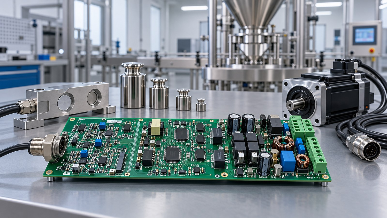
Table of Conent
Table of Conent
A weighing filler PCB must preserve a microvolt- or millivolt-level load-cell signal while switching motors, valves, solenoids, heaters, and industrial communications nearby. The design succeeds when the measurement path, digital control, and servo-power path are partitioned by current flow and coupling mechanism, then reconnected only at deliberate interfaces with filtering, shielding, isolation, and a controlled grounding plan.
Accuracy cannot be secured by choosing a high-resolution ADC alone. Load-cell excitation, ratiometric conversion, connector and cable behavior, reference routing, return-current geometry, power sequencing, servo transients, firmware filtering, mechanical vibration, calibration, and production test all affect the delivered weighing result. PCB manufacturing must preserve those design controls through stackup, component sourcing, assembly, inspection, programming, and machine-level validation.
Partition the controller by signal energy and return current
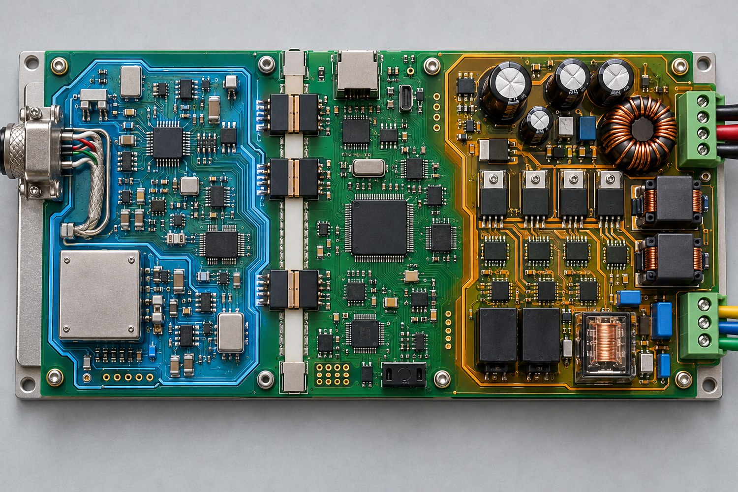
The most useful partition separates the low-level bridge measurement chain from the switching power chain. The sensor zone should contain the shielded load-cell connector, input protection chosen for leakage and capacitance, differential filtering, low-noise amplifier or programmable-gain ADC, excitation/reference circuitry, and quiet local supplies. Servo drivers, relays, solenoid outputs, switching regulators, bulk energy storage, and motor connectors belong in a power zone with short high-current loops.
A digital control zone can connect the two, but it should not become an uncontrolled return path. Identify where analog, digital, chassis, protective-earth, and power returns meet. Splitting copper without understanding current flow can force a sensitive signal across a gap or create a large loop. The aim is not “more ground planes”; it is a predictable path for every signal and disturbance current.
Define zones in the schematic, layout rules, stackup, assembly drawing, and test plan. A coordinated PCB assembly workflow must preserve the same component options, isolation boundaries, shield terminations, creepage constraints, and thermal interfaces that the electrical design assumes.
Build the load-cell measurement as a complete signal chain
A resistive load cell is commonly configured as a Wheatstone bridge whose differential output changes with force. The signal is small relative to industrial noise, so the PCB must treat excitation, reference, input filtering, gain, ADC conversion, and calibration as one system rather than independent blocks.
Analog Devices’ CN0608 reference design describes a ratiometric arrangement in which the load-cell excitation also serves as the ADC reference. Changes in excitation then affect bridge output and reference together, reducing their effect on the conversion result. The note also explains that a 6-wire load cell can sense the actual bridge excitation at the sensor, which can reduce error from cable resistance when the architecture supports it.
Ratiometric conversion does not cancel every error. Input offset and drift, reference buffering, resistor matching, thermoelectric effects, connector resistance, cable pickup, common-mode range, aliasing, vibration, and the load cell’s own nonlinearity and creep remain relevant. TI’s bridge-measurement application brief discusses AC excitation as one method for reducing offset and drift in compatible converters; it is a design option, not a universal requirement.
Document the load-cell type, rated output, excitation range, cable configuration, full-scale differential input, expected common mode, sample rate, filter response, settling time, overload behavior, and calibration method. These parameters determine component values and test limits that the manufacturer must not change casually.
Control servo noise at its source and coupling path
Servo interference can couple conductively through shared supplies and returns, capacitively through changing voltages, inductively through high di/dt loops, or radiatively through cables and enclosure openings. A fix must target the dominant path. Adding a filter without understanding the path can mask a symptom, slow a control signal, or move noise elsewhere.
Minimize the loop area of switching devices, DC-link capacitors, gate-drive paths, and motor-current returns. Keep motor and brake wiring physically separated from load-cell wiring. Route differential sensor pairs together, avoid unnecessary stubs, preserve impedance and reference continuity where edge rates require it, and terminate cable shields according to the enclosure and EMC plan. Provide a low-impedance chassis connection near cable entry when the system architecture calls for it.
Use filtering that matches real spectral content and required response time. Input RC filters should be balanced so common-mode interference does not convert into differential error. Common-mode components, feedthrough capacitors, ferrites, or isolated interfaces may help in the right location, but their voltage, current, leakage, saturation, temperature, and surge behavior must be verified. Place protection components so the transient path reaches chassis or the intended return without crossing the quiet measurement area.
Plan power integrity for measurement and motion together
The weighing channel and servo system share a machine even when their rails are separated. Motor acceleration, regenerative events, brake switching, solenoid release, and emergency-stop transitions can cause supply dips, overshoot, ground movement, and resets. Review the full energy path from incoming power through protection, conversion, distribution, local decoupling, loads, and returns.
Define allowable rail ripple and transient behavior at the actual devices, not only at the power connector. Keep high-current copper wide and short, account for connector and via resistance, and place bulk and high-frequency decoupling according to the current loop they serve. Sensitive references and analog supplies may require filtering or dedicated regulation, but they still need controlled sequencing and a known discharge path.
Test the worst credible combinations: zero and full load, motor start and reversal, rapid indexing, valve switching, communication activity, brownout, emergency stop, and power recovery. If the design files and operating sequence are ready, share the PCB data, BOM, load-cell interface, servo loads, quantities, and test conditions for a coordinated DFM and assembly review. The review should expose layout, sourcing, thermal, and test assumptions before tooling and material are committed.
Convert the electrical partition into manufacturable PCB rules
The fabrication package should make the critical geometry visible. Specify stackup, copper weights, controlled impedance where applicable, minimum spacing derived from the actual voltages and environment, via structures, isolation slots, copper-to-edge limits, and any chassis-contact or shielding features. Do not expect a fabricator to infer safety or EMC intent from net names.
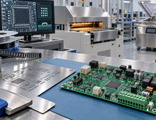
Assembly review should focus on mixed-process risk. Precision analog parts may have leakage, handling, or cleaning sensitivities, while large connectors, relays, inductors, heat-spreading components, and power terminals create high thermal mass. Stencil design, paste volume, reflow profile, selective-solder or through-hole processes, cleaning, conformal coating, and rework limits must fit both groups.
Protect calibration and configuration integrity. Identify programmed devices, calibration constants, serial-number relationships, and any trim or matching requirements. The manufacturing handoff framework is useful here: the released BOM, placement data, firmware, assembly drawings, and test instructions must describe one configuration.
Choose inspection and test by failure mode
No single inspection proves weighing accuracy and servo robustness. AOI can find visible placement and solder defects. X-ray can provide evidence for hidden joints. Electrical testing can catch selected opens, shorts, values, and programming conditions. Functional testing must show that the measurement and motion interfaces work together under defined loads.
Start production test with safe power-up, rail checks, current limits, firmware identity, configuration, communications, and I/O. Verify bridge excitation, ADC zero and span response, noise over a defined time and bandwidth, channel stability, fault detection, and recovery. Then exercise servo enable, motion commands, encoder feedback, valves or actuators, and interlocks while observing weight readings for unacceptable disturbance.
A programmable bridge simulator or traceable calibration fixture can provide repeatable electrical stimuli, while known test weights verify the complete mechanical measurement chain. Use both when the risk justifies it. Define fixture revision, instrument requirements, warm-up, settling, sample count, units, limits, software version, data retention, and failure disposition.
The controller reliability test framework shows how margin, thermal, power-cycle, connector, communication, and fault-recovery tests complement basic functional acceptance. Adapt the stresses to the weighing filler’s duty cycle and environment rather than copying printer-specific limits.
Validate accuracy in the assembled machine
Bench accuracy is not sufficient if the installed machine adds cable length, structural vibration, airflow, temperature gradients, grounding paths, or motor noise. Validate zero, span, repeatability, corner or load-position behavior where applicable, creep, warm-up, tare, overload recovery, and dynamic filling performance under the operating sequence.
For commercial weighing applications in the United States, regulatory requirements may apply beyond internal process-control needs. NIST identifies the 2026 edition of Handbook 44 as the current set of specifications, tolerances, and technical requirements for weighing and measuring devices. The applicable code, jurisdiction, device type, accuracy class, installation, and official test procedure must be determined by qualified compliance stakeholders; a PCBA test cannot by itself establish legal-for-trade compliance.
Record calibration coefficients with the product configuration they belong to. Prevent a firmware update, ADC substitution, reference change, load-cell change, or mechanical modification from silently invalidating calibration. Define which changes require recalibration, partial regression, EMC testing, safety review, or formal requalification.
Use NPI gates to protect the volume build
A production-representative pilot should use the intended PCB source, components, stencil, programs, reflow or soldering process, cleaning, inspection, programming, fixture, and work instructions. Set exit criteria before starting: closed DFM actions, approved material, first-article verification, passed measurement and servo tests, controlled rework, and delivery of required records.
The gated NPI-to-volume method applies directly to weighing controllers. Release quantity in stages, tie every correction to a revised controlled item, and keep open risks visible. Review component lifecycle and approved alternates early using the component-risk prioritization method, especially for precision converters, references, isolators, servo-control devices, power modules, and proprietary connectors.
Traceability depth should match containment and investigation needs. Associate board revision, firmware, calibration data, critical component lots, process records, inspection, functional-test results, rework, and shipment identifiers at the level justified by product and contractual risk. When the release package is controlled, provide the fabrication, assembly, sourcing, programming, calibration, and acceptance-test files for a complete PCB assembly evaluation. The resulting scope should state assumptions, responsibilities, records, and unresolved engineering questions.
Conclusion
A reliable weighing filler PCB does not choose between load-cell accuracy and servo power. It gives each function a controlled electrical and physical path, then proves their interaction under the machine’s real operating sequence. Partition by return current and coupling mechanism, use a complete ratiometric measurement strategy where appropriate, control power and shielding, and convert every critical design assumption into a manufacturing or test requirement.
Production readiness comes from the chain of evidence: released files, qualified materials, repeatable assembly, calibrated stimuli, machine-level tests, controlled changes, and traceable results. That chain protects both measurement integrity and motion control when the design moves from a working prototype to repeatable volume builds.
Latest Blog
Contact Info
Phone: +86-755-82882936
Email: [email protected]
WhatsApp: +86-13570802455
Wechat: +86-13570802455
Address: 2nd floor,D Bldg.,Electric Link Technology Bldg.,Gongming,Guangming New Dist.,518106 Shenzhen, China