
Continuous Inkjet Controller NPI: A Gated Path to Volume Production
Table of Conent
Table of Conent
Moving a continuous inkjet controller from NPI to volume production requires a controlled product baseline, not simply a larger purchase order. The practical path is to freeze the released PCB, BOM, firmware, configuration, mechanics, and test requirements; close DFM and sourcing risks; prove the assembly and programming process on a pilot lot; and authorize each ramp stage only when objective exit criteria are met.
A prototype that prints correctly is necessary evidence, but it does not prove repeatability. Volume readiness depends on stable documentation, producible tolerances, material availability, representative functional tests, traceability, controlled changes, and a feedback loop that converts pilot findings into the next release. The following framework helps engineering, operations, and procurement build those controls before defects or shortages are multiplied by production quantity.
Establish a controlled production baseline
The first production baseline must describe one unambiguous product configuration and feed a controlled PCB assembly workflow. Release Gerber or ODB++ data, drill files, the fabrication drawing, stackup and impedance requirements, BOM, approved alternates, centroid data, assembly drawings, firmware binaries, programming instructions, configuration tables, test specifications, labels, and revision history as one coordinated package.
Prototype teams often tolerate temporary jumpers, hand-selected components, manually loaded settings, bench-only cables, or undocumented rework. Each exception must be eliminated, formally incorporated into the design, or preserved as a controlled manufacturing instruction. The PCB design-transfer checklist explains why fabrication, assembly, firmware, and test files must identify the same revision before a build is released.
Create a release matrix that assigns ownership and approval for every controlled item. It should state who can approve a substitute, change a firmware build, alter a test limit, accept a deviation, or authorize rework. File names alone are weak control; use revision identifiers, effective dates, and an approved release record that can be tied to the manufacturing order.
Translate continuous inkjet functions into manufacturing risks
A continuous inkjet controller usually connects digital processing, high-voltage or precision printhead drive functions, encoder inputs, pumps and valves, temperature or pressure sensing, communications, user interfaces, and safety interlocks. The exact architecture varies by printer, so the NPI plan should derive risks from the schematic, interfaces, power tree, package mix, and operating environment rather than from a generic printer-board template.
Review power sequencing, grounding, isolation boundaries, creepage and clearance requirements, connector keying, shielding provisions, thermal paths, sensitive analog routing, high-current returns, and test access. On the assembly side, identify fine-pitch parts, bottom-terminated packages, large thermal pads, mixed thermal mass, through-hole or press-fit connectors, coating or cleaning constraints, and components that can be damaged by reflow, washing, programming, or fixture contact.
Convert each material risk into a purchasing rule and each process risk into an inspection or test control. A risk register should name the failure mode, consequence, prevention, detection method, owner, and closure evidence. It is more useful than a broad statement that the board will receive “standard inspection.”
Close DFM, stencil, panel, and test-access questions before the pilot
DFM closure should produce dispositions, not a list of observations. Confirm the fabricator’s stackup against impedance and copper requirements, review drill and annular-ring relationships, solder-mask clearances, copper-to-edge conditions, panel rails, tooling holes, fiducials, depaneling stress, component-to-edge spacing, and any routing that depends on controlled return paths.
For assembly, reconcile every BOM line to the footprint, polarity, rotation, package height, moisture sensitivity, and placement process. Stencil aperture decisions should address thermal pads, fine-pitch devices, small passives, connectors, and components with different paste-volume needs. Panel support and tooling should protect the board from flex during printing, placement, reflow, selective soldering, depaneling, and test.
Design-for-test review must happen while layout changes are still possible. Provide accessible ground and power points, programming access, fixture alignment features, and test points for signals that cannot be verified through connectors. If a net cannot be measured directly, document how functional behavior will prove it and what fault coverage remains.
Stabilize the BOM and sourcing model
The ramp cannot be stable if the material definition changes between lots. Mark approved manufacturer part numbers, do-not-substitute items, qualified alternates, customer-supplied parts, source restrictions, lifecycle concerns, packaging requirements, and any date-code or lot-control rules that are technically justified.
Rank processors, FPGAs, printhead-interface devices, isolated transceivers, precision references, power modules, connectors, sensors, and programmed parts by the consequence of shortage or substitution. The component obsolescence risk method provides a practical way to combine supply exposure with redesign and qualification time. Review alternates before production pressure turns a sourcing question into an uncontrolled engineering change.
Agree on the material model as part of the release: turnkey, consigned, or hybrid. Define excess and noncancelable inventory, attrition, shortage handling, customer-owned stock, return rules, and the evidence required before a substitute is installed. If the baseline and ramp quantities are ready, share the released PCB files, BOM with alternate rules, target lot sizes, and required test coverage for a coordinated manufacturing review. The review should expose sourcing assumptions and engineering questions before the pilot material is committed.
Build a pilot that tests the production process
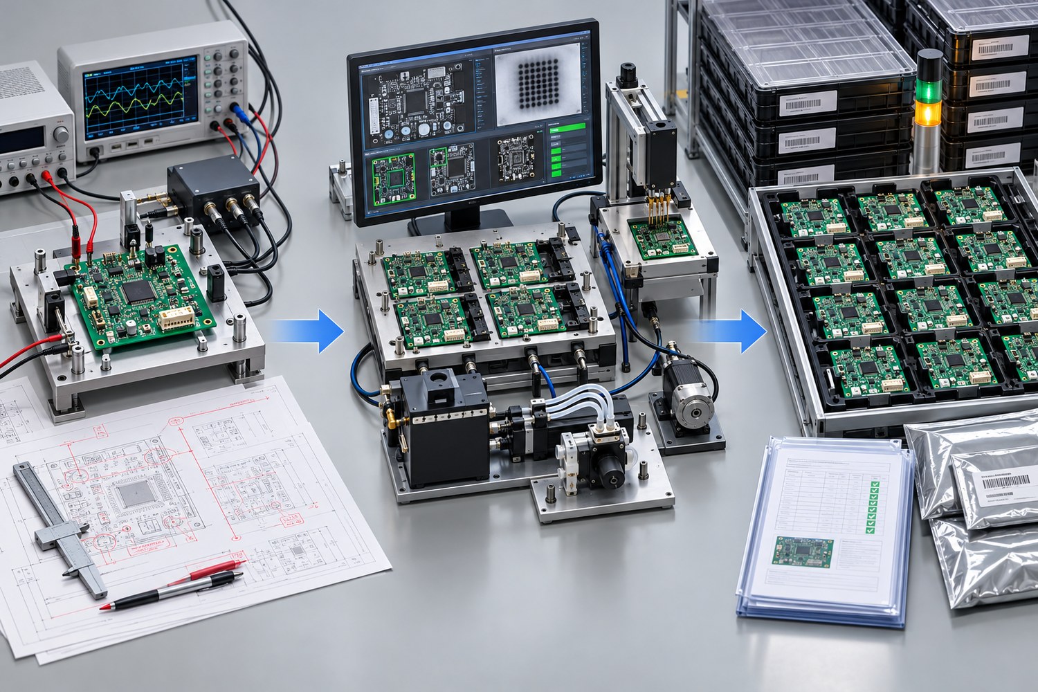
The pilot lot should use the intended fabrication source, components, panel, stencil, machine programs, thermal profile, assembly sequence, inspection flow, programming method, fixtures, work instructions, and data records. A hand-built engineering sample cannot qualify an automated volume process if its materials and methods are different.
Define pilot exit criteria before the lot starts. Typical gates include approved DFM dispositions, complete material, first-article verification, correct firmware and configuration, successful programming verification, inspection coverage for visible and hidden joints, passed electrical and functional tests, documented defects, approved rework, and delivery of the required build record. Quantity alone does not define a pilot; the objective is to exercise and learn from the intended process.
Use staged authorization when practical: approve the first assembly before building the balance, then approve the pilot results before ordering volume. This limits exposure when orientation, footprint, paste, thermal, firmware, connector, or fixture problems appear. It also preserves clear evidence about which correction produced the acceptable result.
Separate workmanship acceptance from product function
Assembly workmanship and product performance are different acceptance layers. IPC’s official release notice explains that J-STD-001J covers soldering process and material requirements while IPC-A-610J covers post-assembly acceptance. The applicable standard, revision, product class, addenda, and customer-specific criteria must be stated in the purchase and build documents.
The current IPC document revision table is the appropriate place to verify revision status instead of relying on an old drawing note or supplier brochure. Workmanship standards do not define whether a controller produces the correct printhead waveform, interprets encoder pulses correctly, drives pumps or valves safely, recovers from faults, or preserves configuration data. Those behaviors require a product-specific test specification.
Select inspection by failure risk. AOI can evaluate visible placement and solder features. X-ray can provide evidence for hidden joints and voiding where relevant. Electrical methods can check selected opens, shorts, values, or nets. None of these replaces a representative functional test, and functional test does not automatically reveal every marginal solder joint. Record the coverage and limits of each method.
Design functional test around continuous inkjet failure modes
A credible functional test verifies the controller at its interfaces under defined conditions. Start with safe power-up, rail values, current limits, sequencing, firmware identity, and stored configuration. Then exercise communications, encoder and trigger inputs, printhead control outputs, pump and valve drivers, temperature or pressure channels, alarms, interlocks, watchdog behavior, shutdown, and restart recovery as applicable to the design.
Use validated simulated loads when a real printhead or fluid system is too expensive, variable, or unsafe for production testing. The fixture specification should identify load values, tolerances, protection, pin mapping, calibration or verification needs, software version, expected responses, measurement units, pass/fail limits, and result storage. Include fixture self-checks so a damaged cable or load does not falsely condemn good boards.
Where final acceptance includes print quality, define the printer hardware, printhead, ink or fluid condition, substrate, encoder speed, pattern, environment, and measurable criteria. A visual “looks good” judgment is not repeatable enough for a volume gate. The layered controller acceptance framework shows how configuration checks, safe power-up, I/O simulation, and representative machine operation can build evidence in sequence.
Use pilot data to set the volume ramp gates
The pilot review should connect every defect or delay to a disposition. Separate design issues, documentation errors, material problems, process defects, programming failures, fixture faults, and handling damage. Update the controlling file, instruction, program, or test limit; do not rely on memory or an email thread to carry the correction into the next lot.
Choose ramp gates that match the product and risk. A typical sequence is engineering validation, production-representative pilot, limited release, then normal volume. For each gate, state the approved revision, allowed quantity, open risks, required records, stop conditions, and authorization owner. Do not set universal yield thresholds without defining the denominator, defect categories, rework treatment, and measurement period.
Capacity review should include constrained equipment, fixture count, programming time, functional-test cycle, inspection bottlenecks, rework capacity, material replenishment, and engineering support. A process can be technically capable yet unable to meet the expected mix or schedule. Compare those assumptions with tooling, nonrecurring charges, excess material, and logistics using the PCB quote total-cost framework.
Preserve traceability and control changes after release
Traceability should support containment and investigation, not collect data without a purpose. IPC-1782 defines risk-based levels for manufacturing and supply-chain traceability agreed between user and supplier. Decide which board revision, component lots, process records, firmware, configuration, inspection, test results, rework, and shipment data must be associated with a work order, lot, or serial number.
NIST’s 2026 manufacturing traceability meta-framework emphasizes organizing and linking provenance data while allowing selective disclosure. For an OEM and PCBA supplier, the practical lesson is to agree on stable identifiers, retention, access, and the questions that records must answer during a shortage, defect investigation, counterfeit concern, or field event.
After release, no BOM, PCB, firmware, fixture, program, test limit, or critical process change should enter production without review of effectivity and requalification. Define notification thresholds and emergency-deviation rules before they are needed. When the complete ramp package is ready, provide the controlled fabrication, assembly, programming, quantity, traceability, and acceptance-test requirements for a full PCB assembly evaluation. A useful response should identify assumptions, unresolved risks, and the evidence required at each release gate.
Conclusion
Continuous inkjet controller volume production is achieved by proving a controlled system, not by repeating a successful prototype. Freeze the product baseline, close DFM and material risks, exercise the intended assembly process on a pilot lot, verify workmanship and printer-specific function separately, and release larger quantities only when documented exit criteria are satisfied.
The strongest NPI plan leaves a traceable chain from engineering intent to material, process, firmware, test evidence, and shipment. That chain makes changes visible, limits exposure when a problem occurs, and gives engineering, procurement, and manufacturing a common basis for the next production decision.
Latest Blog
Contact Info
Phone: +86-755-82882936
Email: [email protected]
WhatsApp: +86-13570802455
Wechat: +86-13570802455
Address: 2nd floor,D Bldg.,Electric Link Technology Bldg.,Gongming,Guangming New Dist.,518106 Shenzhen, China