
PCB Design Automation: Script ERC, DRC and Manufacturing File Release
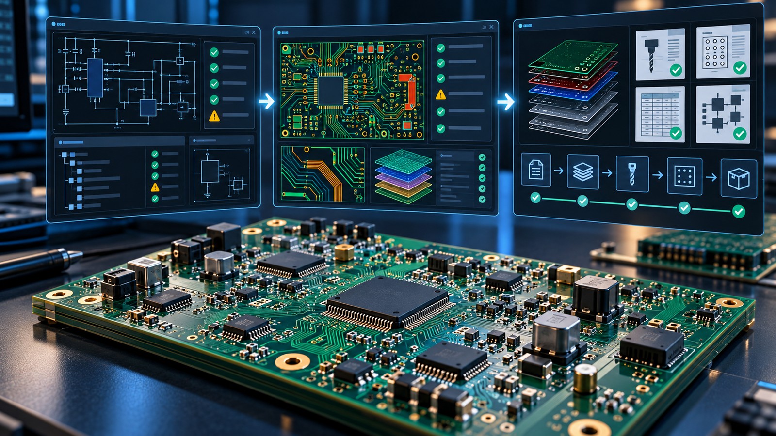
Table of Conent
Table of Conent
PCB design automation should make every release repeatable, reviewable, and difficult to misconfigure. The safest pattern is to automate three connected stages: electrical and physical rule checks, generation of fabrication and assembly outputs, and verification of the released archive. A script or job should fail when a required check fails, when an expected file is missing, or when the output differs from the approved configuration.
Altium Designer, KiCad, and legacy Autodesk EAGLE workflows offer different automation surfaces, but the manufacturing objective is the same. Keep rules and output settings under version control, run them against a known design revision, and preserve reports plus checksums with the release. Automation accelerates a controlled process; it should not silently approve waivers, change design intent, or replace an independent CAM review.
Define the release contract before writing automation
A reliable pipeline begins with a release manifest. List every expected artifact, the command or job that creates it, and the condition that allows the workflow to proceed. Separate bare-board fabrication data from assembly, sourcing, documentation, and test data so a missing file is easy to identify.
For fabrication, the contract may require Gerber X2 or another approved intelligent format, NC drill and route data, a fabrication drawing, stackup, netlist, impedance notes, and a readme. For assembly, it commonly adds a BOM, approved substitutions, component placement data, assembly drawings, paste layers, variant definitions, and test requirements. The format decision still needs supplier confirmation; use the Gerber, ODB++, and IPC-2581 comparison to align the automated output with the receiving toolchain.
Store this contract beside the design sources. Treat filenames, units, origins, layer names, output format revisions, and variant identifiers as controlled inputs. A script that generates the wrong package consistently is not a successful automation.
Build quality gates for ERC and DRC
Rule checks should produce machine-readable status and a retained report. Configure electrical rule checking (ERC) for schematic connectivity and pin behavior, then run design rule checking (DRC) against the physical board constraints. Decide which violations block release, which documented exclusions are permitted, and who can approve a waiver.
The gate should fail on a nonzero violation result rather than merely creating a report. It should also detect stale inputs: unfilled copper zones, an unsynchronized schematic and board, unresolved footprint changes, or a variant that does not match the selected assembly output. Do not parse only a human-readable “passed” line if the tool provides a dependable exit code or structured report.
Altium documents batch DRC as part of its rule-driven validation workflow, including validation through Output Jobs and project release. KiCad 9 provides command-line ERC and DRC operations, with options that can return a violation-dependent exit code, in the official KiCad command-line interface. Pin the software version because commands, rule behavior, and report schemas can change between releases.
Automate Altium Designer releases with OutJobs first
In Altium Designer, an Output Job file is the primary reusable configuration for manufacturing outputs. It can group fabrication, assembly, documentation, BOM, export, and validation outputs, with mappings to output containers. Altium’s Output Job documentation explains that OutJobs store these settings with the project and can include ERC and DRC reports.
Start with an OutJob before adding custom code. Define project-relative sources, required variants, destinations, and validation reports. Place the OutJob under version control and review changes like source changes. If an organization uses a managed release process, configure validation to stop the release when the checks fail.
Use scripting only for gaps around the standard release mechanism, such as normalizing filenames, building a manifest, hashing artifacts, copying approved non-native documents, or comparing the generated package with the contract. Altium’s official scripting documentation supports automating repetitive tasks and custom exports, but a custom script should not duplicate a supported OutJob feature without a clear reason.
Before approving a production handoff, provide the design revision, controlled OutJob or export configuration, BOM, placement data, drawings, quantity, and test requirements for a combined fabrication and assembly data review. The review can then compare the generated package with the actual build scope instead of checking isolated Gerber files.
Use KiCad CLI and jobsets for repeatable outputs
KiCad’s command-line interface can run schematic ERC, board DRC, and manufacturing exports without interactive dialogs. A pipeline can call kicad-cli sch erc, kicad-cli pcb drc, and the required export commands for Gerber, drill, position, IPC-2581, ODB++, STEP, PDF, or other supported outputs. KiCad jobsets can group multiple jobs into one reusable release definition.
Prefer documented CLI commands and jobsets for release automation because they are easier to run in continuous integration and easier to audit than UI macros. Set explicit output directories, layer lists, units, and format options. Capture the KiCad version and command output in the manifest. Make the pipeline delete or isolate the previous build directory before generation only when the exact workspace target has been validated; otherwise stale files can make an incomplete run look complete.
Python plugins remain useful for editing assistance and specialized board analysis, but the API choice matters. KiCad states that the SWIG-based pcbnew bindings are deprecated as of version 9 and recommends the stable IPC API for modern plugin development in its PCB Python bindings notice. Keep release logic on documented interfaces where possible, and test migrations before a KiCad major-version upgrade.
Treat EAGLE scripts and ULPs as a legacy migration concern
Standalone Autodesk EAGLE is no longer a current subscription workflow. Autodesk states that EAGLE stopped being available and supported on June 7, 2026, while qualifying perpetual-license installations can continue on their existing machines. Autodesk recommends migrating EAGLE schematics, boards, and libraries to Fusion Electronics, as described in its EAGLE retirement FAQ.
Existing EAGLE script and User Language Program (ULP) automation may still be valuable as migration evidence. Inventory every script, ULP, CAM job, design-rule file, library dependency, and generated artifact. Record which outputs are contractually required, then reproduce and validate that behavior in the supported Fusion Electronics environment or another selected ECAD platform. Do not assume that opening a legacy design proves the old automation produces identical results.
Verify the package after generation
Output generation is not the final gate. Build a second stage that inspects the package independently of the command that produced it. The checks should be deterministic and should leave evidence that a reviewer can follow. For a turnkey PCB assembly service, the verified package should connect fabrication data with sourcing, placement, variant, inspection, and test inputs.
- Confirm the design identity. Record project, board or assembly number, revision, variant, source commit, ECAD version, and automation version.
- Compare the file inventory. Fail on missing required files, unexpected duplicate layers, zero-byte files, or unapproved extras.
- Inspect geometry and counts. Verify board outline, layer count, drill tools, plated and non-plated holes, component count, net count, and coordinate origin against approved expectations.
- Cross-check assembly data. Reconcile BOM designators with placement records and drawings, including do-not-populate states and approved variants. A controlled PCB assembly variant workflow prevents one automation run from mixing populations.
- Render human-review files. Generate plots or PDFs for copper, mask, legend, assembly sides, and fabrication notes. Apply a consistent assembly drawing checklist rather than treating a successful export as approval.
- Hash and archive. Create checksums only after the package passes, and archive the manifest, reports, inputs, and output bundle together.
Design continuous integration around safe failure
A PCB release pipeline should stop clearly and preserve diagnostics. Run it in an isolated workspace with a pinned ECAD version or a documented build agent. Prevent parallel jobs from writing to the same output directory. Use stable artifact names or a revision-specific directory, then publish artifacts only after every required check passes.
Keep credentials and licensed-tool configuration outside the repository. Limit scripts to the project workspace, validate paths before removing old outputs, and never let cleanup logic target a broad directory. Record tool exit codes, report locations, and the exact manifest comparison that failed. A failed job should leave enough evidence to distinguish a design violation from a missing license, an unsupported command, or a filesystem problem.
Automation also needs change control. Review rule-file and output-job changes separately from routine layout edits. Test a pipeline update on a known reference project whose expected layer, drill, net, BOM, and placement counts are already documented. If a software update changes output syntax or geometry, block production release until the difference is explained.
Release checklist for engineers and buyers
- Identify the approved ECAD version, project revision, assembly variant, and release owner.
- Run ERC and DRC with blocking thresholds and retain the reports.
- Generate fabrication, assembly, sourcing, documentation, and test outputs from controlled settings.
- Verify the archive with an independent inventory and geometry/count checks.
- Confirm that BOM, placement, drawings, and variant data describe the same population.
- Map inspection and test requirements to methods, limits, and records using a requirement-led PCB test plan.
- Store checksums and release evidence with the exact package sent to the manufacturer.
Make automation serve the manufacturing decision
The strongest PCB design automation does more than save clicks. It proves which design revision was checked, which rules were applied, which files were generated, and whether the package matches the approved build. Altium OutJobs, KiCad CLI and jobsets, and migrated EAGLE/Fusion workflows can all support that outcome when their versions and configurations are controlled.
For a production build, assemble the final Gerber or intelligent data package, drill files, BOM, pick-and-place data, drawings, variant rules, quantity, and test requirements. AssyPCB can use those inputs to evaluate the released PCB assembly package, identify missing manufacturing information, and align fabrication, component sourcing, assembly, and test assumptions before pricing and build planning.
Latest Blog
Contact Info
Phone: +86-755-82882936
Email: [email protected]
WhatsApp: +86-13570802455
Wechat: +86-13570802455
Address: 2nd floor,D Bldg.,Electric Link Technology Bldg.,Gongming,Guangming New Dist.,518106 Shenzhen, China