
Gerber vs ODB++ vs IPC-2581: Choose the Right PCB Manufacturing Data
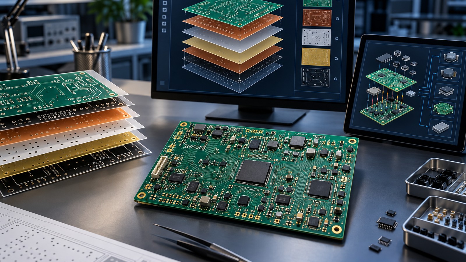
Table of Conent
Table of Conent
Choosing among Gerber, ODB++, and IPC-2581 is not a contest to find one universally superior file format. The practical choice is the format that your PCB design system can export correctly, your manufacturer can import without translation loss, and both teams can validate under revision control. Gerber remains a dependable, widely supported layer-based handoff. ODB++ and IPC-2581 can carry a richer connected product model, but their value depends on the actual export and import implementations in your supply chain.
The best release package therefore starts with supplier capability, not a format slogan. Confirm the supported revision, required companion files, CAM validation process, and how exceptions will be documented. Then archive the exact files that were reviewed and approved. This guide compares the three approaches and turns the choice into a release decision you can audit.
What a manufacturing data package must accomplish
Regardless of container, a fabrication release must communicate copper geometry, solder mask and legend, drilled and routed features, board outline, layer order, finished thickness, material expectations, surface finish, controlled impedance requirements, and any special construction notes. An assembly release adds the bill of materials, approved substitutions, component coordinates, polarity and orientation, assembly drawings, paste data, and test requirements.
No format automatically resolves an ambiguous drawing, an incomplete stackup, or conflicting revisions. Treat the digital dataset as one controlled part of the procurement package. Use a disciplined PCB assembly drawing checklist to identify instructions that belong in drawings or notes, and manage population differences through a documented PCB assembly variant process.
Gerber: familiar, inspectable, and broadly interoperable
Gerber represents PCB image layers, with current extensions supporting attributes that identify layer functions and features. The format is maintained by Ucamco, which publishes the Gerber specifications and Gerber Job File schema. A typical fabrication package combines Gerber layers with drill/rout data and documentation such as a fabrication drawing and stackup. Assembly deliverables are usually separate.
Its strength is operational familiarity. Nearly every board shop can visualize and process a conventional Gerber package, and engineers can review each rendered layer independently. That same file-by-file structure creates a release-management burden: omitted layers, mismatched origins, unclear drill units, duplicate outlines, and stale companion documents can survive unless a preflight check catches them.
Use Gerber when
- Your supplier explicitly prefers it and provides a clear release checklist.
- Your CAD export is proven and the receiving CAM system validates attributes correctly.
- You need a human-readable layer review that fits an established approval process.
- Your team can control the accompanying drill, netlist, drawing, stackup, BOM, and placement files as one revision.
Gerber is not inherently incomplete, but the completeness of the package depends heavily on companion files and disciplined naming. Do not assume an X2 attribute or job file will be consumed simply because your CAD tool exported it; confirm the manufacturer’s actual workflow.
ODB++: an integrated manufacturing product model
ODB++ packages geometry and manufacturing intelligence in a structured dataset instead of relying primarily on separate image layers. The official ODB++Design overview describes a model spanning fabrication, assembly, and test information. This connected structure can preserve relationships among nets, components, features, and process data that otherwise have to be reconstructed by CAM engineering.
That richer context can improve automated checks and reduce manual data correlation. It does not guarantee a frictionless handoff. Export options, supported ODB++ versions, compression, naming conventions, and importer behavior can differ. Some organizations also require a parallel human-review artifact or drawing set for contractual approval.
Use ODB++ when
- Your CAD-to-supplier path is tested with a specific export and import version.
- The supplier uses the embedded product intelligence for DFM, assembly preparation, or test engineering.
- You want to reduce manual reconstruction of connectivity and component relationships.
- Your archive process can preserve the complete dataset and its release manifest.
Before adopting it as the primary handoff, run a pilot board through both sides of the toolchain. Compare net counts, apertures, drill spans, component identities, and outline interpretation against the approved design. If you want an independent review of your first production package, send the native design output, drawings, BOM, placement data, and test expectations for a manufacturing-data package review before the release is frozen.
IPC-2581: open XML for connected fabrication and assembly data
IPC-2581 is an XML-based standard intended to exchange PCB and assembly product information across design and manufacturing. IPC’s IPC-2581 Revision C announcement describes data sufficient for tooling, manufacturing, assembly, and inspection, while the IPC-2581 Consortium maintains implementation resources and promotes interoperability.
Its standards-based schema and capacity for rich product data make it attractive for teams seeking a neutral exchange model. As with ODB++, the specification’s capability is not the same as complete implementation. Confirm which revision and content level the exporter produces, what the manufacturer imports, and whether all required objects survive translation.
Use IPC-2581 when
- Both parties support the same revision and have validated their specific tools.
- You need a structured exchange that can include fabrication and assembly intelligence.
- Your organization favors a standards-based, machine-readable archive.
- You can verify critical content rather than trusting a successful import message alone.
Gerber vs ODB++ vs IPC-2581 at a glance
| Decision factor | Gerber package | ODB++ | IPC-2581 |
|---|---|---|---|
| Core structure | Layer-oriented files plus companions | Integrated product model | Structured XML product model |
| Typical ecosystem | Very broad CAM familiarity | Strong where an established ODB++ toolchain exists | Strong where both sides support the same IPC revision |
| Connectivity and attributes | Available through attributes and companion data; verify consumption | Designed to retain connected manufacturing intelligence | Schema can carry connected fabrication and assembly data |
| Human layer review | Straightforward with common viewers | Usually needs a compatible viewer or derived plots | Usually needs a compatible viewer or derived plots |
| Main release risk | Missing or mismatched companion files | Exporter/importer version or interpretation differences | Revision, content-level, or implementation gaps |
These are tendencies, not guarantees. A clean Gerber package can outperform a poorly validated intelligent dataset, while a proven ODB++ or IPC-2581 workflow can remove repetitive interpretation. Score the actual toolchain, not the theoretical capacity of the standard.
A practical selection framework
- Ask the manufacturer what is native. Record accepted format, revision, compression, naming, origin, units, and mandatory supporting documents.
- Assess export fidelity. Confirm your CAD license and configuration export the fields you expect, including stackup, component, net, and drill attributes.
- Match the data to the buying scope. Bare-board fabrication, turnkey assembly, consigned assembly, and test development do not require identical information.
- Run an independent comparison. Render copper, mask, legend, outline, and drills; compare counts and critical dimensions with the source design.
- Freeze one release. Put the dataset, drawings, BOM, approved vendor list, placement file, revision note, and checksums in one controlled archive.
When suppliers are otherwise comparable, include data handling in the commercial decision. The effort required to normalize an incomplete release can affect lead time and engineering charges, just as materials, testing, and logistics affect the total cost behind PCB assembly quotes. For a turnkey build, also confirm that your selected PCB assembly service can carry variant, traceability, and test records from the approved release through production.
Release validation checklist
- Open the final export in a viewer independent of the authoring canvas.
- Check layer count, polarity, order, board outline, panel intent, and route geometry.
- Verify plated and non-plated holes, slots, backdrills, blind/buried vias, and units.
- Compare net counts and flag shorts, opens, or unconnected copper introduced during translation.
- Confirm stackup, materials, copper weights, finished thickness, impedance notes, and finish.
- For assembly, validate BOM identities, approved substitutions, coordinates, rotations, polarity, and do-not-populate states.
- Map inspection and test requirements to measurable limits and retained records using a requirement-led PCB test plan.
- Resolve every discrepancy in writing before tooling or component procurement begins.
Create a manifest with project name, assembly number, revision, export date, CAD version, format revision, file list, and cryptographic checksum. Keep the approval record with the archive. If manufacturing engineering modifies data for panelization or process compensation, preserve the supplier’s derived revision separately and maintain traceability to the customer release.
The right answer is a verified workflow
Choose Gerber when broad compatibility and established layer review are decisive. Choose ODB++ when a validated integrated toolchain will use its connected manufacturing intelligence. Choose IPC-2581 when both parties support the same standards-based exchange and have proven the required content. In all three cases, drawings, acceptance criteria, revision discipline, and independent validation remain essential.
For production planning, provide the complete fabrication and assembly release package—not just the preferred container—so the manufacturer can check compatibility before commitment. AssyPCB can evaluate a complete fabrication and assembly release package against the intended build, identify missing manufacturing inputs, and align the accepted dataset with the quoted scope.
Latest Blog

Contact Info
Phone: +86-755-82882936
Email: [email protected]
WhatsApp: +86-13570802455
Wechat: +86-13570802455
Address: 2nd floor,D Bldg.,Electric Link Technology Bldg.,Gongming,Guangming New Dist.,518106 Shenzhen, China