
Filling Machine PCB Prototypes: Reduce Delays in Parts and Assembly
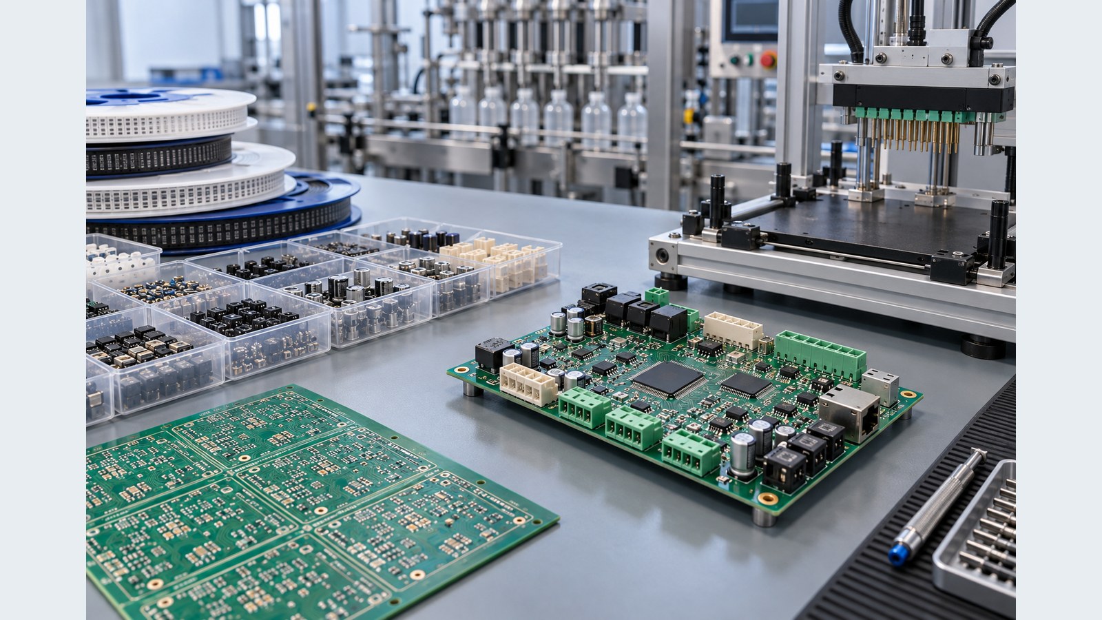
Table of Conent
Table of Conent
Filling Machine PCB Prototypes: Reduce Delays in Parts and Assembly
A filling machine PCB prototype can miss its build date even when the board layout is finished. The usual causes are not mysterious: an unapproved component alternate, a long-lead connector, inconsistent BOM data, late mechanical changes, missing programming files, or a test plan that appears only after assembly. For a servo-driven filler, these delays are especially costly because the controller must coordinate motion, valves, pumps, sensors, safety inputs, operator interfaces, and communications.
The fastest reliable prototype is therefore not the board with the shortest quoted assembly time. It is the build whose parts, fabrication data, assembly instructions, firmware, and test scope are ready at the same time. This guide shows how engineering and procurement teams can shorten low-volume lead time without hiding technical risk or sacrificing traceability.
Freeze the build package before chasing a fast date
Start with one controlled release package. It should include Gerbers or another approved manufacturing-data format, drill files, stackup and fabrication notes, a BOM with manufacturer part numbers, centroid data, assembly drawings, schematics, programming files, and a written test scope. The revision identifiers on those files must agree. If a prototype has variants, define each fitted and do-not-populate position explicitly.
IPC describes IPC-2581 as an intelligent design-to-manufacturing data exchange that can carry fabrication, assembly, and inspection information. A shop may accept Gerber, drill, BOM, and placement files instead, but the same principle applies: manufacturing should receive one coherent dataset rather than reconstructing intent from conflicting email attachments.
Use the PCB assembly drawing checklist to capture polarity, orientation, special handling, selective soldering, press-fit, adhesives, staking, cleaning, coating, and inspection requirements that a BOM alone cannot express.
Build a BOM risk table before purchase orders are placed
For each line item, record the approved manufacturer part number, package, value or function, lifecycle status, required quantity including attrition, known lead time, approved alternates, and the person authorized to approve a substitution. Flag single-source ICs, servo and motor-control devices, isolated interfaces, sensors, safety relays, power modules, connectors, and displays. These parts often control the schedule even when they represent only a small fraction of the BOM.
Do not treat a distributor search result as an engineering approval. An alternate must be checked for electrical limits, pinout, package dimensions, thermal behavior, qualification needs, firmware dependencies, and supply-chain authenticity. For capacitors, the printed capacitance value is not enough; the MLCC DC-bias alternate guide explains why effective capacitance under applied voltage can change the result.
Create three buckets: ready to buy, alternate approval needed, and redesign or schedule decision needed. Procurement can act immediately on the first bucket while engineering works the second. The third bucket deserves an explicit decision rather than a last-minute unreviewed substitution.
Use phased procurement without losing configuration control
A phased buy can shorten elapsed time. Long-lead, high-confidence parts may be ordered after schematic and footprint review, while ordinary passives wait for the final release. This only works when the team understands the exposure: early purchasing can create scrap if pinout, package, voltage rating, or mechanical constraints change.
Maintain a reservation list that links every early-buy item to the intended PCB revision and build quantity. Separate customer-supplied inventory from assembler-purchased parts. Record lot codes or date codes when the application requires them. If reels are shared across variants or projects, reserve enough usable quantity after setup and placement attrition.
Before committing an aggressive build date, send the fabrication files, BOM, placement data, quantity, target date, and known alternates through the prototype PCBA review request. A manufacturability and sourcing review can identify the true schedule drivers before components and boards enter separate, incompatible timelines.
Run DFM and DFA while parts are being sourced
Fabrication review and assembly review should run in parallel with sourcing, not after all parts arrive. Check trace and spacing rules, annular rings, drill-to-copper clearances, solder-mask registration, copper balance, board edge clearances, panel rails, tooling holes, fiducials, and impedance requirements. For assembly, check paste apertures, component spacing, polarity marks, bottom-termination packages, thermal pads, connector access, and the order of SMT, through-hole, press-fit, and manual operations.
IPC’s DFM guidance notes that manufacturability checks draw from design, fabrication, land-pattern, current-carrying, and soldering standards. The applicable product class and acceptance criteria still need to be agreed for the project. A generic “IPC compliant” note does not define every tolerance, inspection method, or customer exception.
For a filling-machine controller, include the mechanical environment. Confirm connector keying, mating access, enclosure clearances, heatsink interfaces, mounting-hole hardware, cable bend radius, sensor shielding, and separation between noisy drive circuits and low-level measurement inputs. A prototype that works only on an open bench can still fail integration.
Choose the assembly route around the real bottleneck
Low quantity does not automatically mean hand assembly is faster. A board with fine-pitch ICs, bottom-termination packages, or many passives usually benefits from a normal stencil, placement, and reflow process even for a small batch. Hand operations may still be appropriate for low-volume connectors, transformers, terminal blocks, wiring, or engineering changes.
Ask how the supplier will handle minimum order quantities, partial reels, moisture-sensitive devices, baking, component preparation, selective soldering, press-fit, depanelization, cleaning, and rework. Confirm whether excess material will be returned, stored, or consumed, and how substitutions are documented. The PCBA quote breakdown helps separate component cost, assembly operations, tooling, and nonrecurring engineering rather than comparing only a headline unit price.
A practical schedule should identify the gating path: bare boards, a critical component, stencil and fixture preparation, programming, or functional-test readiness. Adding overtime to a non-gating operation will not move the delivery date.
Prepare firmware and test assets before the first board exits reflow
Prototype assembly is not complete when soldering is finished. Provide the bootloader or production image, programming method, device configuration, security or serialization requirements, and a record format for the programmed version. If calibration constants or machine-specific settings are not available yet, define a controlled temporary state and a later update procedure.
Plan inspection and test by defect risk. IPC identifies IPC-A-610 and J-STD-001 as complementary references for assembly acceptability and soldering-process requirements. Contract documents should state the revision, class, and customer-specific criteria. Visual acceptance does not replace electrical test, firmware verification, or load testing.
At minimum, define unpowered short checks, current-limited power-up, supply-rail limits, programming verification, communications checks, sensor-input stimulation, and safe representative loads for valve, pump, or servo-control outputs. Record board revision, BOM revision, firmware version, fixture revision, measured values, and the disposition of failures. Decide in advance which tests run on every unit and which remain engineering characterization.
Use a release gate that exposes missing inputs
A concise readiness gate prevents false starts. The owner of each item should mark it ready, open, or blocked, with the next decision and due date.
- Fabrication data, stackup, drill data, and drawing share one revision.
- BOM entries have manufacturer part numbers and approved substitutions.
- Centroid data, polarity, rotation, and assembly variants are verified.
- Long-lead parts are allocated to the correct revision and quantity.
- Panelization, stencil, tooling, depanelization, and special processes are agreed.
- Firmware, programming hardware, and configuration records are available.
- Inspection and test limits identify fixtures, loads, sampling, and pass/fail rules.
- Mechanical interfaces and harness assumptions are documented.
For variant-heavy machines, the PCB assembly variants guide provides a practical way to control fitted options, DNP positions, BOMs, drawings, firmware, and labels without creating ambiguous build instructions.
What to send for a fast prototype review
Send the complete data set, not only Gerbers. Include the target quantity, desired delivery window, critical component constraints, approved sourcing channels, alternates already reviewed, required PCB construction, assembly class, firmware and programming method, test coverage, mechanical interfaces, and packaging needs. Identify any parts you will supply and their confirmed location and quantity.
The prototype PCB assembly service overview shows how fabrication, component sourcing, SMT and through-hole assembly, programming, inspection, and test fit into one coordinated build. The value of one supplier is not merely fewer purchase orders; it is one revision-controlled schedule with visible dependencies.
When those inputs are ready, submit them through the complete filling-machine controller PCB quote request. Ask the engineering review to return open items, approved alternates, the gating path, and the assumptions behind the promised date. That creates a schedule the team can manage rather than a date that depends on unspoken exceptions.
Conclusion
Fast filling machine PCB prototypes come from removing waiting between disciplines. Freeze a coherent release package, classify BOM risk early, source long-lead parts with controlled exposure, run DFM and DFA in parallel, and prepare firmware and test assets before assembly finishes. The result is not only a shorter prototype cycle. It is a build record that can support troubleshooting, the next revision, and a cleaner transfer into low-volume production.
Latest Blog

Contact Info
Phone: +86-755-82882936
Email: [email protected]
WhatsApp: +86-13570802455
Wechat: +86-13570802455
Address: 2nd floor,D Bldg.,Electric Link Technology Bldg.,Gongming,Guangming New Dist.,518106 Shenzhen, China