
Filling Machine Controller PCB: Valve Timing and Washdown
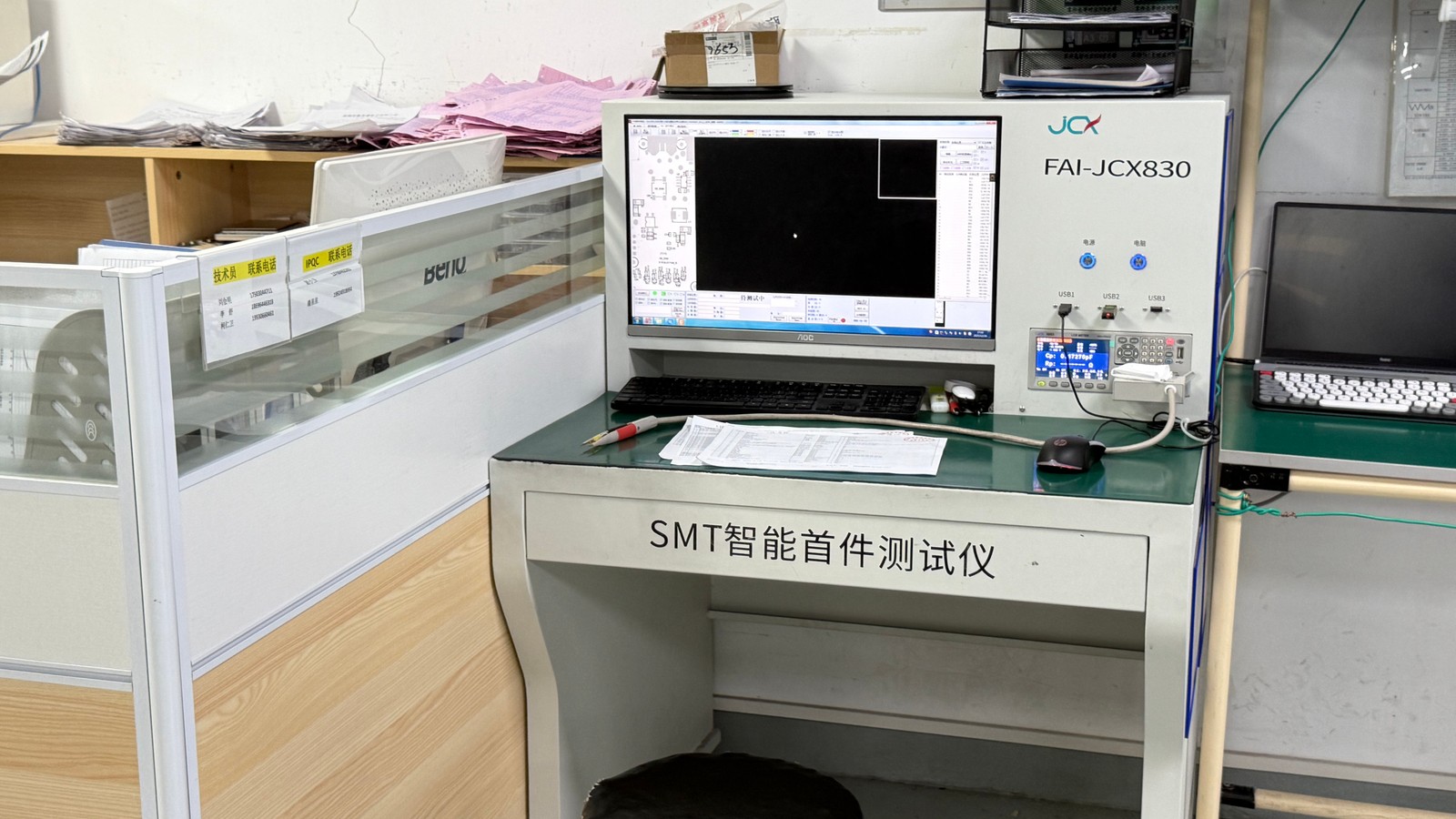
Table of Conent
Table of Conent
A filling machine controller PCB should be checked against the loads it actually controls and the environment its enclosure actually admits. Start with the valve, pump, sensor, and drive interfaces; then verify electrical behavior, physical response, and measurement stability under representative operating combinations. A clean command waveform alone does not prove that a valve has stopped delivering liquid.
Washdown adds a separate boundary: the enclosure, cable entries, connectors, board cleanliness, and any protective coating must work together. Define the exposure and functional acceptance limits before qualification. Neither a coating label nor a successful dry power-up establishes machine-level reliability. The practical design checklist is therefore an evidence plan connecting the controller to the complete filling system.
Define the controller boundary before choosing protection
Protection and test requirements depend on whether the PCB switches a load directly or only commands another controller. Identify that boundary for every output before selecting drivers, suppression components, or test fixtures.
A board driving a solenoid must accommodate coil current, stored magnetic energy, switching repetition, supply variation, and the selected turnoff path. A board sending commands to an external servo drive has a different responsibility: interface levels, signal timing, fault feedback, cable conditions, and behavior when the drive becomes unavailable. Do not apply a coil-driver checklist to a logic-only interface.
Document the actual harness, connector pinout, return paths, shielding arrangement, and power-source impedance. Name the conditions under which outputs must remain inactive during boot, firmware download, communication loss, and restart. Machine safety functions need their own defined architecture and assessment; an ordinary firmware output-off command is not evidence of a safety function.
Use the filling-machine prototype readiness guide for the broader parts and build-package workflow. Here, the additional release question is whether the assembled controller has an agreed electrical and functional boundary that the test setup can reproduce.
Measure valve turnoff beyond the command edge
Valve turnoff is a sequence of electrical, mechanical, and fluid events. Measure those events separately before attributing a fill error to software timing or changing the driver clamp.
For a directly driven coil, the TI solenoid-driving application note explains why a parallel freewheeling diode produces relatively slow current decay, while a higher opposing discharge voltage can reduce decay time. Faster decay brings voltage, energy, and thermal constraints. The driver, clamp, coil insulation, and switching duty must remain within their applicable ratings.
Use the selected coil’s conditions and the complete discharge circuit. The TI clamp-energy guidance connects stored inductive energy with clamp selection; its equations and examples do not establish a universal clamp voltage for a filling machine. Check repetitive operation as well as a single pulse, and determine where the released energy is dissipated.
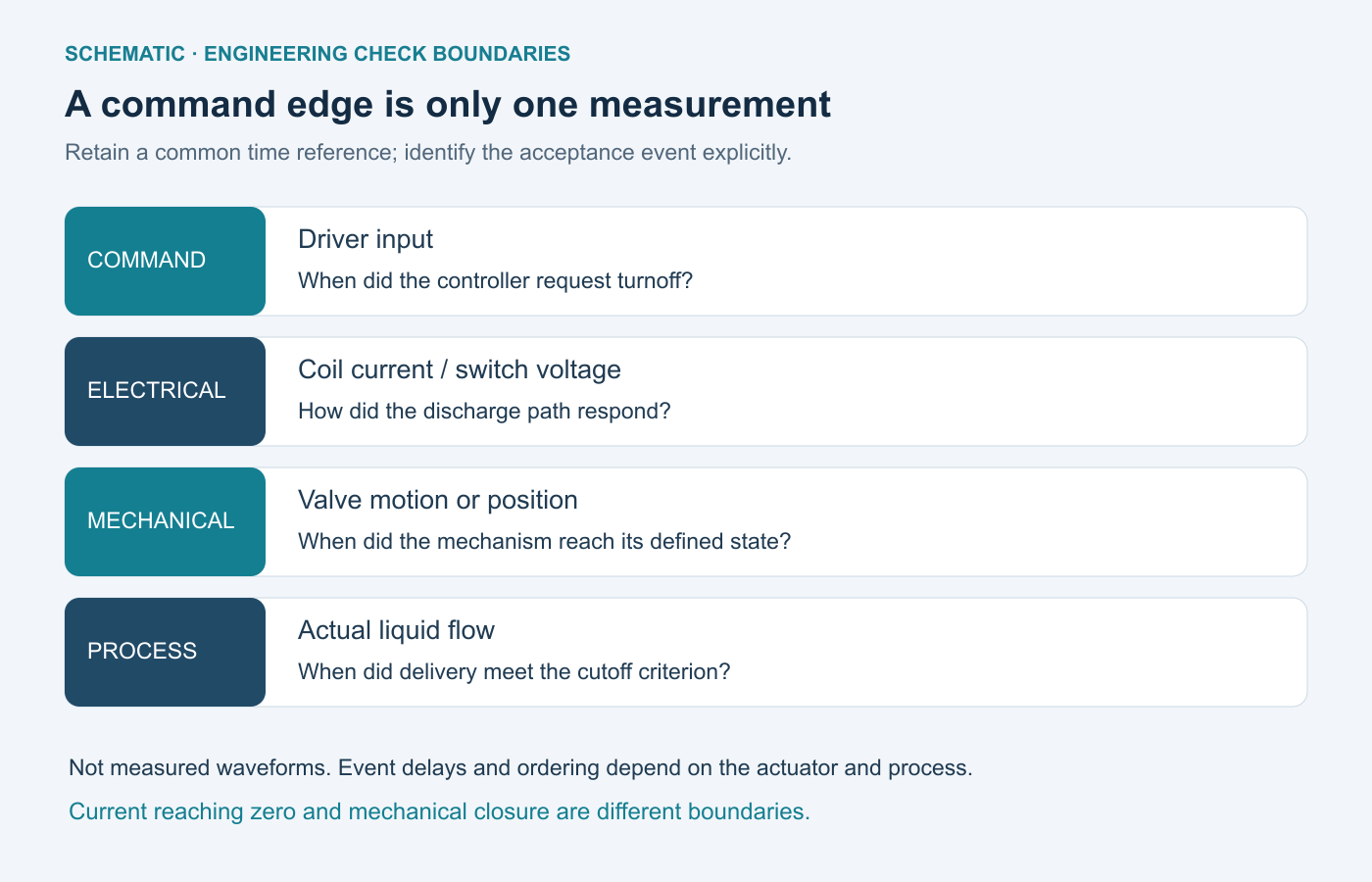
Capture the command and coil current on a common time reference. Add an appropriate position or motion observation when available, and measure actual flow cessation with the machine team’s agreed method. A valve can begin closing before coil current reaches zero; mechanical travel, pressure, fluid properties, and downstream volume can still affect the final delivery. Specify which event defines the acceptance limit.
For example, a hypothetical controller may produce repeatable command pulses while the delivered quantity varies after a coil or harness substitution. Compare the current decay and physical cutoff before adjusting the recipe. Otherwise, software compensation can conceal a changed actuator response that will reappear under another operating condition.
Check sensor readings during the worst load combinations
Evaluate sensor performance while the relevant loads switch, using the installed return paths and sampling schedule. Quiet-bench measurements cannot establish stability during simultaneous valve and pump activity.
Identify the coupling path before changing the layout. Supply movement, shared return impedance, cable coupling, and communication activity can produce different symptoms. Blanket ground splitting is not a substitute for tracing the current loop and checking the actual reference seen by the measurement circuit.
| Interface or load | Stimulus and observation | Decision supported |
|---|---|---|
| Directly driven valve coil | Record command, current, switching-node voltage, and applicable physical response across approved supply and load conditions. | Confirm driver stress and the event used for timing acceptance. |
| Weight or flow measurement | Apply a stable reference while the relevant valve and pump combinations switch; retain readings and sample timestamps. | Distinguish input drift or switching interference from a real process change. |
| External motion drive | Exercise command, enable, feedback, and defined fault states through the representative harness. | Verify the interface contract without assuming the PCB controls motor power. |
| Controller supply and communication | Observe rail behavior, resets, message errors, and recovery while the selected loads operate together. | Identify an integration failure that isolated channel tests would miss. |
Agree on allowed sensor deviation, recovery behavior, and the observation window before testing. If a measurement is deliberately blanked during switching, verify that the machine can still meet its control requirement with the remaining samples. A filtered display can hide disturbances that the control algorithm still sees.
If the assembly test scope cannot represent these interactions, share the load and interface brief for scope review with the harness definition, critical waveforms, board revision, and intended quantity. OrinewPCB can review the requested build and test requirements; machine-level timing and fluid validation must remain explicitly assigned.
Treat washdown protection as an enclosure-to-board system
Choose board protection from the exposure that can reach the electronics, including maintenance and cooling periods. A controller inside a protected cabinet may need a different approach from one near repeatedly wetted connectors.
Describe the cleaning agent, concentration, temperature, contact duration, application method, and whether the equipment is energized. Include cable entries, connector mating state, enclosure joints, drainage assumptions, and the route by which liquid or condensation could reach a sensitive circuit. These are product requirements, not details that a PCB assembler should infer from the word “washdown.”
The HumiSeal coating brochure discusses environmental protection alongside material selection, contamination, cleaning, and drying. Coating should not be assumed to create an impermeable enclosure. Residues or moisture beneath an inadequately prepared coating can undermine the intended protection.
Use the MacDermid Alpha coating guidelines and the selected product’s current data sheet to establish the material and application process. Do not copy one generic thickness, cure schedule, or chemical-resistance claim into every controller drawing. The conformal-coating selection and specification guide covers the broader release details, including keepouts and inspection evidence.
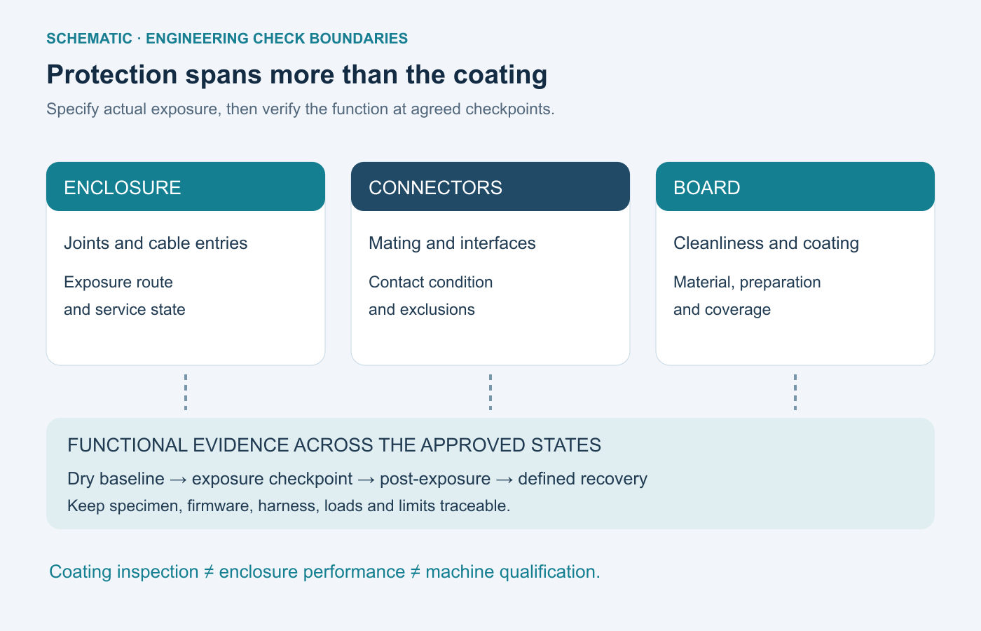
Pay particular attention to serviceable interfaces. A coating requirement that blocks a mating contact, test point, or approved repair can create a new problem. Specify the protected areas and exclusions, and check the actual assembled geometry rather than assuming the coating process reaches or avoids every surface.
Repeat functional checks across environmental states
Use the same defined functional baseline before exposure and at the agreed later checkpoints. A visual inspection after drying cannot answer whether leakage, drift, resets, or timing changes occurred while the circuit was biased.
Moisture, electrical bias, and ionic contamination can contribute to electrochemical migration: conductive material grows between conductors and can create leakage or a short. This mechanism makes contamination control and the powered state relevant to the qualification plan. OrinewPCB’s short explanation below illustrates that mechanism; it is not a qualification record for a filling machine.
| State | Functional evidence | Required boundary or decision |
|---|---|---|
| Dry baseline | Record valve response, sensor reference readings, rail behavior, and communication results. | Freeze firmware, recipe, loads, harness, and instrument setup for comparison. |
| Agreed exposure, powered only where specified | Monitor the permitted functions and failure indicators under the approved procedure. | Product team defines exposure, limits, monitoring access, and safe test arrangement. |
| Immediate post-exposure checkpoint | Repeat the specified functional checks; document visible condition and any changed readings. | Separate an operating failure from cosmetic observations or an untested assumption. |
| Defined recovery checkpoint | Compare the same signals after the agreed recovery interval and conditions. | Record persistent and recovered deviations; recovery does not erase an earlier failure. |
Write numerical limits and any permitted recovery into the approved protocol before collecting data. Do not choose a convenient humidity cycle or pass threshold after seeing the result. Keep the exposure history and raw measurements tied to the specimen identity so a later component or coating change can be assessed against the same baseline.
Separate product qualification from production acceptance
Qualification establishes whether the design and protection strategy meet the intended application. Production acceptance screens the agreed build defects and functional requirements. The two plans can share fixtures or signals, but they answer different questions.
A manufacturing first-article inspection can confirm selected assembly characteristics without proving flow cutoff or environmental endurance. Likewise, a dry functional test can verify programming and channel operation without demonstrating resistance to moisture-assisted leakage. Define the coverage and exclusions rather than calling every successful check “fully tested.”
The PCB test-planning guide helps connect requirements, methods, fixtures, and retained records. Specify which checks run on every unit, which use an agreed sample, and which belong to engineering qualification. Assign ownership for machine fixtures, calibrated references, approved loads, firmware, failure disposition, and retest rules.
Changes to the coil, suppression network, connector, cleaning process, coating, or firmware can invalidate different parts of the evidence. Review the affected boundary instead of assuming a familiar part number or unchanged board outline preserves qualification.
Release the evidence with the assembly scope
Release a filling machine controller PCB when its electrical boundary, operating combinations, protection requirements, and acceptance records agree. The essential outcome is a traceable argument from controller behavior to the intended machine condition, with untested assumptions still visible.
Separate board-level deliverables from machine integration work when comparing suppliers. The full-turnkey PCB assembly scope provides a starting point for coordinating fabrication, sourcing, and assembly; specialized load simulation and environmental qualification require an explicitly agreed scope.
For an assembly project, provide the controlled assembly package and test requirements through OrinewPCB’s project inquiry form. Include fabrication files, BOM, placement data, assembly notes, firmware requirements, quantity, and the relevant load and exposure evidence so the build, sourcing constraints, and requested test work can be reviewed together.
Technical sources accessed October 21, 2026. TI SLVAE59A was revised in April 2022; use the current selected-component and coating-product documentation for the released design.
Latest Blog
Contact Info
Phone: +86-755-82882936
Email: [email protected]
WhatsApp: +86-13570802455
Wechat: +86-13570802455
Address: 2nd floor,D Bldg.,Electric Link Technology Bldg.,Gongming,Guangming New Dist.,518106 Shenzhen, China