
PCB Functional Safety: Design and Manufacturing Evidence
Table of Conent
Table of Conent
PCB functional safety depends on how an electronic system detects faults and controls their consequences. A well-manufactured board is necessary evidence, but it does not establish a Safety Integrity Level (SIL) or Automotive Safety Integrity Level (ASIL) by itself. IEC 61508 provides a general framework for electrical, electronic and programmable electronic safety-related systems; ISO 26262 addresses safety-related electrical and electronic systems in road vehicles within its defined scope. The applicable standard, safety function and allocated requirements must be established before PCB layout and supplier selection.
For a board entering production, the practical task is to preserve the connection between the safety concept, hardware implementation, approved components, manufacturing revision and verification results. This guide maps those engineering and procurement decisions. It is a release-planning framework, not a clause-by-clause compliance assessment or a claim that OrinewPCB holds functional-safety certification.
Choose the standard from the application and safety function
The equipment context determines the standard; the PCB technology does not. A multilayer board used in an automotive controller and a similar board used in industrial equipment can have different safety lifecycles, evidence requirements and responsibilities.
IEC 61508-1 covers the general framework for E/E/PE systems performing safety functions. ISO 26262-5 addresses automotive hardware development, including hardware safety requirements, design, architectural evaluation and integration verification. These are distinct contexts, rather than interchangeable purchasing labels.
| Project question | Decision to document | Procurement consequence |
|---|---|---|
| Which application and lifecycle apply? | Identify the governing standard, edition and customer-specific requirements with the system safety owner. | Put that baseline in the statement of work; avoid an undefined “safety-compliant PCB” line item. |
| What safety function reaches this board? | Define the board boundary, interfaces and allocated hardware requirements. | Separate fabrication and assembly acceptance from design verification and system validation. |
| Who accepts the evidence? | Name the responsible design, safety, manufacturing and assessment roles. | Assign document ownership and approval authority before production changes occur. |
Do not translate SIL into ASIL using a simple equivalence table. Similarly, a component intended for a safety application does not automatically confer a system-level rating. The resulting argument depends on its integration, assumptions and verification.
Record the edition explicitly. As checked on October 26, 2026, IEC lists IEC 61508-1:2026 PRV as a pre-release final draft in its voting period, while its lifecycle listing identifies the 2010 edition as valid. ISO lists Part 5:2018 as published with a replacement draft under development. A draft announcement alone is not a reason to silently change a contracted baseline.
Translate the safety concept into reviewable hardware evidence
A board requirement must identify the relevant failure behavior and how the system detects or contains it. “Add a watchdog” is incomplete unless the design also establishes what is monitored, how a fault is reported and what produces the intended response.
IEC 61508-2 addresses safety-related hardware activities, including refining system safety requirements into design requirements and applying measures to avoid or control faults. At PCB level, a useful engineering implementation is a requirements-to-evidence map: requirement identifier, affected circuit, analysis assumption, verification method and responsible owner. The exact work products and rigor follow the project’s applicable standard and safety plan.
Review shared dependencies before relying on redundancy. Two processing channels can still depend on one supply, connector, reset path or environmental exposure. ISO 26262-9 includes dependent-failure analysis within its scope. The board review should therefore ask whether a single disturbance could defeat both the functional path and its diagnostic, rather than merely count duplicated devices.
Device documentation makes this concrete. Texas Instruments’ TMS320F28P55x safety manual discusses external voltage supervision, watchdogs and common dependencies involving power, clock and reset. Those recommendations are specific to the device and application assumptions. They illustrate the questions to ask; they are not a universal circuit recipe for every PCB.
For example, an external monitor may report a fault correctly while the output path remains enabled because the shutdown connection was omitted or configured incorrectly. A useful review follows the entire path from fault detection through output behavior, including startup and recovery. The safety engineer defines the acceptance criteria; the assembler needs a controlled test instruction for the portions assigned to production.
Keep numerical claims attached to their conditions. Failure rates, diagnostic coverage and response times need a documented source and integration basis. Do not reuse an IC-level figure as a board-level result, or treat the presence of a diagnostic pin as proof that the complete application meets its target.
Release the manufacturing package without losing the design assumptions
The manufacturing package should tell a supplier exactly what may change and which decisions require the design owner’s approval. An assembly team cannot preserve an unstated assumption about component variants, programming, calibration or test configuration.
ISO 26262-7 covers production and later lifecycle activities, including their planning. For procurement, translate the agreed production responsibilities into a build package and record list. The following are practical release controls to tailor to the project, not a substitute for the standard’s complete requirements.
If the design package is ready for a manufacturing review, share the released files and safety-related build constraints with the BOM, placement data, quantities and assigned test requirements so fabrication, sourcing, assembly and test assumptions can be reviewed together.
- Link schematic, PCB data, fabrication drawing, assembly drawing and BOM to one released revision.
- Identify components and settings that affect safety assumptions, including approved manufacturer part numbers and substitution restrictions.
- Define programmed software, configuration, calibration and identification data where these affect the delivered assembly.
- State required inspections, production tests, acceptance limits, records and disposition of failed units.
- Specify who approves deviations, repairs, substitutions and changes to test equipment or test software.
A controlled DFM disposition is especially important here. A proposed footprint, spacing or component change may solve a manufacturing problem while changing a design assumption. Record the finding and approval against the affected revision before revised files reach the line.
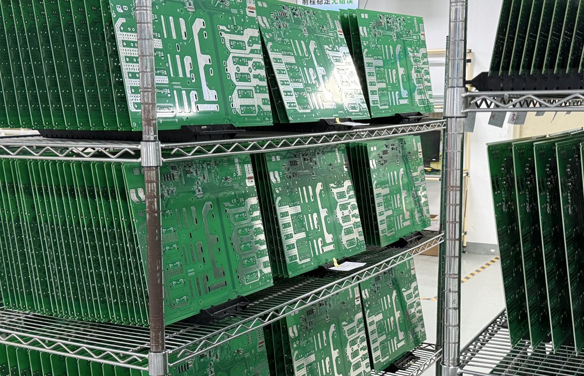
With full-turnkey PCB assembly, responsibility boundaries still need to be written down. Combining fabrication, sourcing and assembly in one purchasing scope does not transfer the OEM’s safety-case decisions automatically.
Separate build inspection from fault-response verification
Inspection evidence answers whether the assembly was built to its released definition. Functional-safety verification must also address the behavior and analyses allocated by the safety concept. A passing optical inspection cannot establish that a diagnostic detects a fault or that the system reaches its required state.
Use a requirements-based PCB test plan to assign each question to an appropriate method. Record what the method can detect and what remains outside its coverage. Treat “tested” as incomplete unless the test revision, limits, result and unit or lot identity are recoverable.
| Evidence layer | Question it can address | What it does not establish alone |
|---|---|---|
| AOI or other specified assembly inspection | Does the inspected assembly match the defined visible acceptance criteria? | Diagnostic coverage, fault-response timing or system-level safety performance. |
| Production electrical or functional test | Does the built unit meet its assigned electrical and functional acceptance limits? | Complete coverage of every failure mechanism or operating environment. |
| Design-level analysis and verification | Are allocated requirements and fault assumptions supported by the planned analysis and verification evidence? | That every production unit was built and configured to that verified baseline. |
| System integration and validation | Does the integrated system perform its safety functions in the defined application? | A replacement for production controls and subsequent change assessment. |
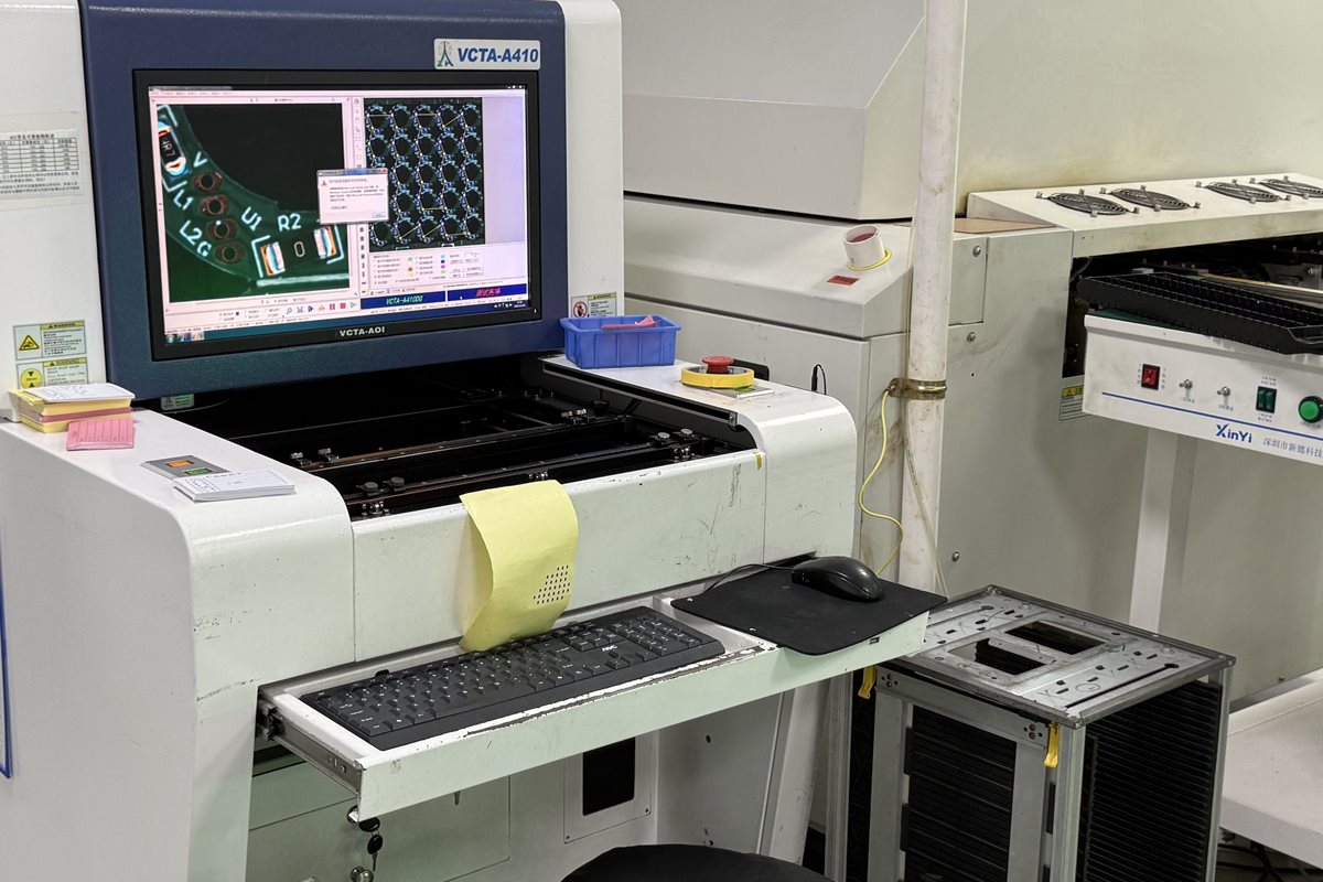
The official OrinewPCB clip below shows an AOI inspection station. It is included to illustrate the manufacturing evidence layer discussed here, not to demonstrate SIL, ASIL, diagnostic coverage or fault-response testing.
Fault-injection or diagnostic verification needs a separate, approved procedure where the safety plan calls for it. Define the injected condition, observation point, expected response and restoration checks. Do not improvise destructive faults on production equipment or infer coverage from a successful normal-operation demonstration.
Production test may exercise selected diagnostic or shutdown functions, but the assigned scope must be explicit. The test owner should explain how fixture behavior, firmware configuration and measurement limits affect the evidence. A fixture that masks a fault or forces an output can create a reassuring pass result while bypassing the behavior under review.
Keep changes and supplier records connected to the safety baseline
A substitution or process change needs an impact decision before it becomes the new production baseline. Matching a package and nominal value does not show that all diagnostic, environmental or failure-behavior assumptions remain valid.
ISO 26262-8 includes distributed-development interfaces, requirements management, configuration management, change management, verification and documentation. A practical handover uses those categories to keep supplier actions connected to the design authority, rather than relying on a general certificate or an email saying “equivalent part approved.”
Consider an illustrative voltage-supervisor substitution. Procurement should send the exact proposed part number and supporting data to the design owner. Engineering then evaluates the characteristics relevant to that circuit, such as thresholds, timing, output behavior and operating conditions, and determines whether analysis or verification must change. This is an example of a review process, not an approval of any particular replacement.
Preserve the link between the approved change and affected units. The unit-history and traceability workflow explains the manufacturing side of connecting identifiers, build revisions and records. For a safety-related project, the safety plan determines which of those records are required, how they are retained and who can accept a deviation.
Before releasing a purchase order, settle three questions: which evidence the supplier must deliver, which changes need prior approval, and which party accepts the completed package. Include any unresolved safety assumptions as open items with owners; do not hide them inside a price comparison.
The useful deliverable is a controlled assembly with a reviewable evidence trail. Board quality, device documentation, safety analysis and system validation each contribute a different part. For a project entering supplier review, provide the controlled assembly package and evidence requirements, including the applicable standard and edition, BOM, placement files, quantities, substitution rules and test scope. That gives the team a basis to clarify the manufacturing quotation without treating it as a promise of system-level certification.
Latest Blog



Contact Info
Phone: +86-755-82882936
Email: [email protected]
WhatsApp: +86-13570802455
Wechat: +86-13570802455
Address: 2nd floor,D Bldg.,Electric Link Technology Bldg.,Gongming,Guangming New Dist.,518106 Shenzhen, China