
MIL-STD-1553 Bus Controller PCBA: Define the Turnkey Build
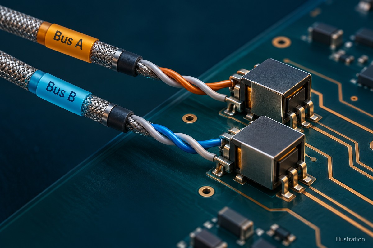
Table of Conent
Table of Conent
A MIL-STD-1553 bus controller PCBA turnkey build should deliver a controlled board configuration and an agreed set of acceptance records. Define whether the order includes bare-board fabrication, component procurement, assembly, programming, the external bus-test network, and serialized results. Price those boundaries explicitly: a populated board, a board that passes internal self-test, and a board exercised against an independent remote terminal are different deliverables.
For OEM hardware, purchasing, and production-test teams, the first decision is who supplies and approves each part of that evidence chain. The controller board, coupling hardware, harness, reference terminal, software, and measurement setup must describe the same configuration. This guide focuses on that manufacturing handoff. The applicable program documents determine protocol revision, workmanship, environmental requirements, and formal validation; neither the interface name nor a component data sheet establishes complete equipment approval.
Define exactly where the turnkey order ends
A useful turnkey scope assigns an owner and a release record to every item needed to build and accept the board. Keep recurring assembly work separate from test-development work and customer-owned equipment. Otherwise two quotes can appear comparable while one omits the only equipment capable of verifying the external interface.
Start with the board boundary: fabrication data, stackup and drawing, BOM, placement data, assembly drawing, connector map, and permitted variants. Then identify items installed outside the board, including bus couplers, cables, terminators, enclosure hardware, and production fixtures. State whether the supplier buys, assembles, stores, maintains, or merely connects those items.
| Boundary | Define before quotation | Required decision or deliverable |
|---|---|---|
| Fabricated and assembled board | Released files, BOM, coupling population, inspection criteria | One approved hardware revision and permitted variants |
| Programmed configuration | Firmware, FPGA or initialization image, loading and verification method | Image identity and configuration record tied to the board |
| External test network | Couplers, harnesses, terminations, reference terminal, instruments | Named owner, approved setup, maintenance and verification duties |
| Acceptance evidence | Test cases, limits, coverage, retained data and disposition authority | Results associated with serial number and test-system revision |
The full-turnkey PCB assembly scope provides the broader fabrication, sourcing, and assembly context. For a 1553 board, add the interface-specific purchasing and test obligations rather than assuming that “functional test included” covers them. A test network supplied by the customer still needs an incoming check, connection instructions, and a route for resolving faults.
Freeze coupling parts and programmed behavior together
Approve the exact physical interface and programmed configuration as one build variant. A footprint-compatible transformer, a different population option, or an initialization-file change can alter what the delivered board does even when its assembly drawing appears unchanged.
Holt’s AN-550 hardware-design resource treats terminal logic, transceiver, isolation transformer, and bus interconnection as linked interfaces. Translate that chain into BOM controls: exact manufacturer part numbers, pin assignments, winding connections, allowed substitutions, and the intended direct- or transformer-coupled configuration. Do not let a buyer infer electrical equivalence from package size.
The manufacturer’s transformer selection resources distinguish isolation transformers from coupling transformers and offer different isolation-transformer ratios. Consequently, “1553 transformer” is an incomplete purchasing description. Require engineering approval of the actual proposed alternate against the selected transceiver circuit, pin map, electrical requirements, package, and environmental conditions before purchase or placement.
Keep installed board components distinct from the coupling equipment in the test harness. Mark fitted and unpopulated options on the assembly drawing, including jumpers and any selectable loads. Preserve the approved connector-to-channel map through placement, inspection, fixture wiring, and test software. The 1553 grounding and isolation review addresses the related layout and return-path decisions; those decisions should reach manufacturing through released drawings, not verbal instructions.
Programming needs the same discipline. Holt’s HI-6130 product information describes optional initialization from an external EEPROM and internal self-test of defined digital functions. This is a device-specific example, not a feature shared by every controller. Where applicable, release the initialization image alongside firmware or FPGA files, with the loading tool, verification method, and approved identity check. Define who can change a message schedule or configuration and how that change becomes effective on a serial-number range.
Once these options are identified, send the BOM and coupling configuration with the assembly files and sourcing restrictions so the build review can resolve procurement assumptions and test responsibilities before materials are committed.
Separate workmanship evidence from bus acceptance
Workmanship acceptance establishes whether the assembly meets its specified construction criteria; it does not establish correct bus traffic. State soldering, inspection, cleaning, coating, and rework requirements independently from the electrical test specification.
The IPC release explaining J-STD-001 and IPC-A-610 separates soldering processes and materials from post-assembly acceptance. Name the contractually applicable revisions, class, addenda, and customer criteria. Select these from the product requirements; do not assign a class, alloy, screening flow, or special qualification merely because the board uses a 1553 interface.
Choose inspection around actual packages and access. Optical inspection can examine visible assembly features. Hidden joints may require an agreed X-ray method; accessible nets may support electrical checks. Inspect transformer orientation, connector identity, polarity, and variant population against controlled data. A correctly marked package still requires the correct part and orientation record.
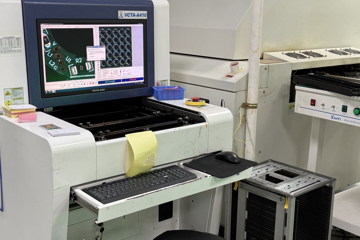
The official OrinewPCB video below shows general factory AOI activity. It provides process context for visual inspection, not evidence that a particular 1553 board passed acceptance.
Complete the agreed inspection before shields, coating, or enclosure operations remove access. If rework changes the interface path, repeat the affected inspection and electrical checks and retain the disposition with the board record.
Prove each channel with an independent bus endpoint
A production test should demonstrate the external path for each required channel, using an independent endpoint and a controlled network. Internal loopback or a passing device self-test cannot, by itself, prove the installed transformer, connector, cable identity, or external network.
Holt’s 1553 protocol and hardware FAQ distinguishes physical-layer requirements from protocol behavior: the bus controller initiates communication and remote terminals respond. Build the test around that relationship. Use a known reference terminal or validated test instrument, then confirm that the commanded channel reaches the intended physical connector and receives the expected independent response.
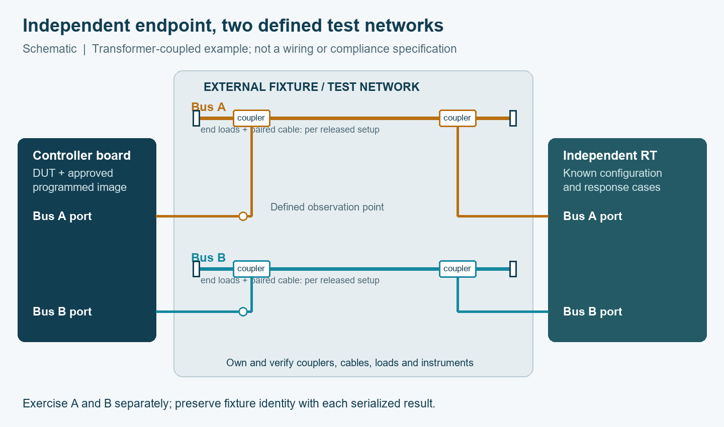
Define the observation point before assigning waveform limits. A voltage measured at a transceiver pin is not automatically comparable to one measured at an external terminal connection. Specify the selected coupling arrangement, cable and load configuration, probe method, instrument settings, supply conditions, and applicable limits. Preserve setup identity so a later measurement can reproduce the acceptance condition.
Qualify the test station before using it to release a lot. A known-good reference board can reveal a broken harness, but agreement between two boards does not prove every failure will be detected. During fixture validation, use approved checks for channel identity, missing responses, and configuration mismatches. Record which defects the method can detect and which remain outside its coverage. Repeat the station check after relevant cable, coupler, software, or instrument changes, so a test-system correction does not silently change product acceptance.
| Risk | Independent evidence | Release action |
|---|---|---|
| A/B connector or fixture mapping reversed | Exercise one selected channel and observe the identified external port and reference endpoint | Correct and reverify the channel map before accepting the lot |
| Incorrect transformer or population option | Part/variant inspection plus defined transmit and receive measurements | Resolve hardware configuration; repeat affected tests after rework |
| Wrong initialization or controller settings | Readback or identity check plus known message transactions | Reload approved data and rerun configuration-dependent cases |
| Missing response or damaged fixture path | Approved no-response case and fixture self-check/reference-board comparison | Separate DUT failure from test-system failure before disposition |
Use the requirement-to-test planning method to assign each case a requirement, stimulus, observation, limit, and retained result. Define expected timeout, retry, channel selection, and recovery behavior from the OEM specification. Do not invent a universal failover sequence or force a fault that the approved setup cannot safely tolerate.
Price repeatable deliveries and close the pilot gate
The pilot gate should close configuration and evidence gaps before recurring production is authorized. Agree on the delivered record and on who pays for fixture development, reference hardware, software licensing, calibration or verification, maintenance, and test changes.
Separate nonrecurring engineering from recurring test time. A quote that includes fixture development but excludes the customer’s reference terminal is different from one that includes a maintained test station. Record ownership and availability of reusable assets, replacement-cable lead time, software access, and the process for transferring the test setup to another approved location.
Before ramp approval, reconcile the delivered hardware revision, component and variant records, programmed-image identity, inspection results, test-system revision, and serialized results. Define stop conditions for missing files, unapproved alternates, invalid fixture checks, and unexplained channel failures. A corrected board should carry both the original failure record and the approved retest evidence.
A complete 1553 turnkey scope connects the physical board, programmed behavior, independent bus tests, and shipment records. When those boundaries are ready, share the complete build and test package with quantities and target delivery requirements to align fabrication, component sourcing, assembly, and acceptance preparation for the pilot.
Latest Blog


Contact Info
Phone: +86-755-82882936
Email: [email protected]
WhatsApp: +86-13570802455
Wechat: +86-13570802455
Address: 2nd floor,D Bldg.,Electric Link Technology Bldg.,Gongming,Guangming New Dist.,518106 Shenzhen, China