
Smart Lock PCB Design: Balance BLE Sleep and Motor Pulses
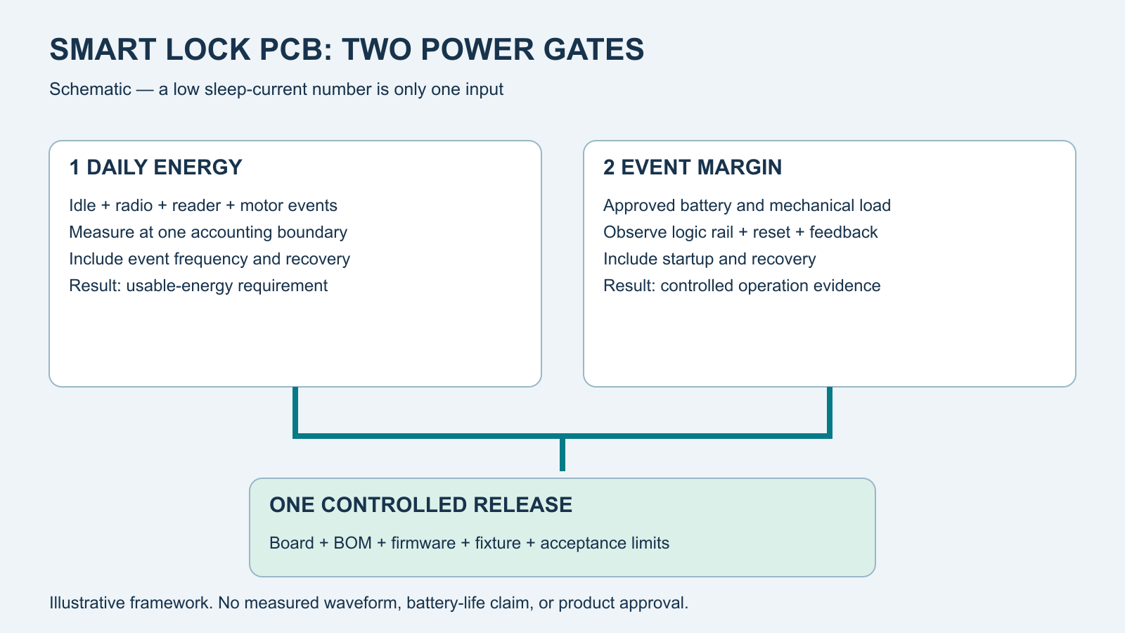
Table of Conent
Table of Conent
Smart lock PCB design needs two separate power checks: enough usable battery energy for the intended service interval, and enough instantaneous supply margin to complete each approved motor operation without losing control. A low BLE sleep-current number proves neither on its own. Build an energy budget from measured operating states and event frequency, then verify battery input, logic voltage, reset behavior, and mechanical feedback during representative motor events. Keep those measurements tied to one battery specification, assembled-board revision, firmware image, and test setup.
This guide focuses on battery-powered locks using Bluetooth Low Energy (BLE) and a motor-driven mechanism. It connects power architecture and layout decisions to a repeatable PCBA acceptance package. Electrical measurements support that package; they do not establish lock security, emergency access, or finished-product safety approval.
Separate battery-life energy from motor-pulse margin
Daily energy and the minimum voltage during an operation answer different questions. A design can have excellent standby consumption and still reset during motor startup; it can also tolerate startup while missing its service-life target. Release criteria need both results.
Record the time spent in idle, advertising, connection, credential processing, indication, motor operation, and recovery. Include unsuccessful attempts and retries where the product requirements allow them. For a repeating event, integrate current over its complete duration to obtain charge, rather than comparing peak heights. Nordic’s current-measurement fundamentals explains why the measurement window changes an event’s average current and why charge is useful for periodic loads.
A hypothetical battery-side example shows the scale: an additional continuous 10 µA consumes 0.24 mAh per day. A rectangular 0.8 A motor event lasting 0.5 seconds consumes about 0.111 mAh; twelve such events consume about 1.33 mAh per day. These invented values illustrate accounting, not a lock specification. Motor usage cannot be dismissed simply because its duration is short.
Keep the accounting boundary consistent. Do not add charge measured on a regulated radio rail directly to charge measured at a different battery voltage. Measure at the battery input, or translate the branches into energy with the relevant conversion losses. Avoid double-counting idle charge already included in an integrated event window.
Compare power architectures at both idle and actuation loads
Select the architecture from the battery operating range and the actual load profile. Regulator quiescent current, light-load behavior, available motor voltage, and transient response matter alongside full-load efficiency.
TI’s smart e-lock power-architecture comparison evaluates linear, boost, and buck arrangements under stated radio and lock-event assumptions. Its results demonstrate that usage and converter losses change the outcome. They do not make one topology universally preferable or transfer a reference design’s battery-life claim to another mechanism.
| Candidate arrangement | Check at idle | Check during motor operation | Decision before layout |
|---|---|---|---|
| Battery-fed motor, regulated logic | Regulator ground current and every always-powered branch | Logic regulator input margin while the shared source is loaded | Confirm both branches across the permitted battery range |
| Boosted motor rail | Shutdown leakage, wake sequence, and unused-rail behavior | Battery-side current, converter limits, and recovery | Compare measured input energy and available mechanical performance |
| Separate or isolated logic supply path | Added control-circuit current and leakage | Hold-up interval, recharge, reverse paths, and control continuity | Demonstrate the benefit against component cost and additional failure modes |
A separate supply path is a candidate to evaluate, not an automatic cure. Its components occupy space and can introduce voltage loss or startup constraints. Define the minimum operating conditions from the selected MCU, radio, memories, sensors, and driver. Lowering a brownout threshold below valid operation is not an acceptable way to pass the check.
Compare sourcing options under those same conditions. An alternative regulator with a matching nominal output can behave differently at light load; a driver substitute can change sleep behavior or fault reporting. Keep these choices in a controlled BOM, using the PCB assembly variant-control guide to separate approved configurations.
Measure standby leakage on the complete assembled board
Verify that the board reaches the intended idle state and that the measurement setup is not supplying or draining it through another connection. A radio datasheet’s sleep current excludes other components and test-fixture paths.
Start from a known firmware configuration and document the enabled wake sources, reader state, LEDs, battery monitor, motor-driver state, and connected interfaces. Nordic’s measurement-setup validation guidance identifies GPIO back-powering, pull-resistor paths, floating inputs, and debugger leakage as possible causes of misleading current readings. Apply the selected device’s documented pin states rather than copying another chip’s configuration.
Measure the complete board, then isolate branches through designed access points where practical. Record what changed and confirm the firmware still runs correctly. Removing code can accidentally change pin configuration or trigger a fault, so a smaller current reading is not automatically an improvement. Disconnect or isolate the debugger as supported, and account for fixture LEDs, level translators, sensing inputs, and external cables.
If the prototype’s sleep budget depends on unresolved component or fixture assumptions, share the BOM, power-state requirements, and measurement boundary with the board files and proposed quantity so the sourcing, assembly, and requested test scope can be assessed together.
Use the instrument range and acquisition window appropriate to the state. Capturing microamp idle and a motor surge may require separate setups; confirm neither saturates nor changes the board’s operation. Keep the supply voltage, range, settling rule, and measurement duration with the result.
Validate motor events at the logic rail and mechanism
Observe the supply and control outcome during the same event. Motor current alone does not show that the MCU remained valid, that the radio recovered, or that the mechanism reached the requested position.
Use a product-owner-approved fixture, load range, and operating sequence. Capture battery-terminal voltage, the relevant logic rail, reset or fault indications, motor current, and the available position signal on a common timeline. Include startup and recovery, not just steady motion. Battery chemistry, state, temperature, contacts, and wiring belong in the test definition; a stiff bench supply represents only its own source conditions.
TI’s electronic-lock motor-control discussion describes position sensing and current-based stall detection. A production threshold still needs characterization against the actual motor, mechanism, and allowed load. Startup and an obstruction can both produce elevated current. Do not interpret every peak as successful end-of-travel, or prescribe prolonged stalling as a generic test.
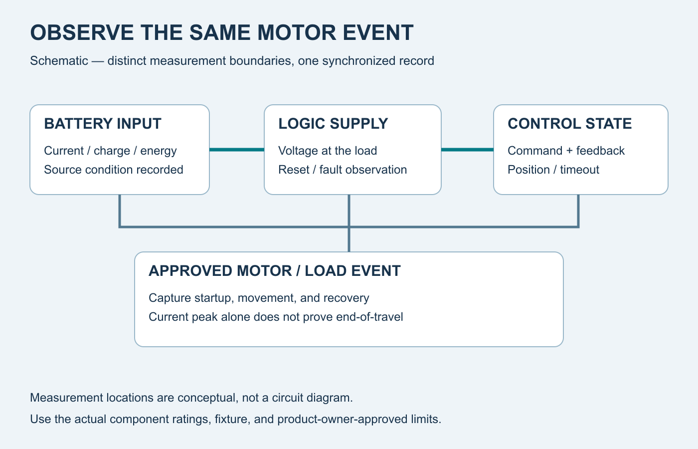
For a hypothetical fault, suppose the motor command starts, logic voltage falls, and reset precedes the reported operation failure. That sequence supports investigating the supply path before changing radio timing. If voltage remains valid but feedback never reaches its defined state, investigate the sensing, drive, or mechanical boundary. The controller fault-isolation guide develops the broader method of separating observations from assumed causes.
Keep the motor-current path out of sensitive measurements
Lay out the driver, local energy storage, and return path as a system. A shared conductor’s voltage drop can affect logic reference or current sensing even when the schematic shows separate nets elsewhere.
The DRV8833 supply recommendations explain that local bulk capacitance depends on motor demand, supply-path inductance, acceptable ripple, and braking behavior, with system testing needed to establish the value. The same device’s layout guidance connects close bypass placement and thermal performance to the physical PCB and package. Follow the actual driver’s instructions; their component values are not universal smart-lock rules.
Review the outgoing and returning motor-current paths together, including connector pins and battery contacts. Keep sensitive sense connections referenced as the selected amplifier or driver requires. Reserve measurement access at the battery input, driver supply, logic supply, and relevant fault or feedback signals before placement becomes fixed. The PCB test-point design guide helps turn those observations into accessible fixtures.
Preserve the selected radio or module’s antenna and ground requirements while arranging power routing. Carry its approved layout constraints into the mechanical assembly review; do not invent a universal antenna clearance or solve every motor interference issue by splitting the ground plane.
Turn the power budget into a controlled PCBA test package
Specify stimuli, limits, and records together so different operators can test the same configuration. Separate a practical production screen from the longer product-qualification program.
| Check | Controlled condition | Record and acceptance basis |
|---|---|---|
| Standby | Released firmware, defined wake and peripheral states, isolated fixture paths | Input current after agreed settling; OEM limit and measurement uncertainty |
| Event consumption | Named radio or motor event, complete acquisition window | Charge or energy at the stated boundary; usage model kept separately |
| Supply continuity | Approved source, load, and event combination | Logic minimum and reset/fault history against component and product requirements |
| Mechanical outcome | Approved fixture and bounded operation | Position, timeout, and recovery result; not inferred from current alone |
| Configuration | BOM, battery, firmware, board and fixture revisions | Traceable result and rules for revalidation after changes |
Release the smart lock board with repeatable acceptance evidence
Approve the energy budget and event-margin evidence before freezing production limits. Carry unresolved conditions into the release record rather than converting a single successful prototype into a battery-life promise.
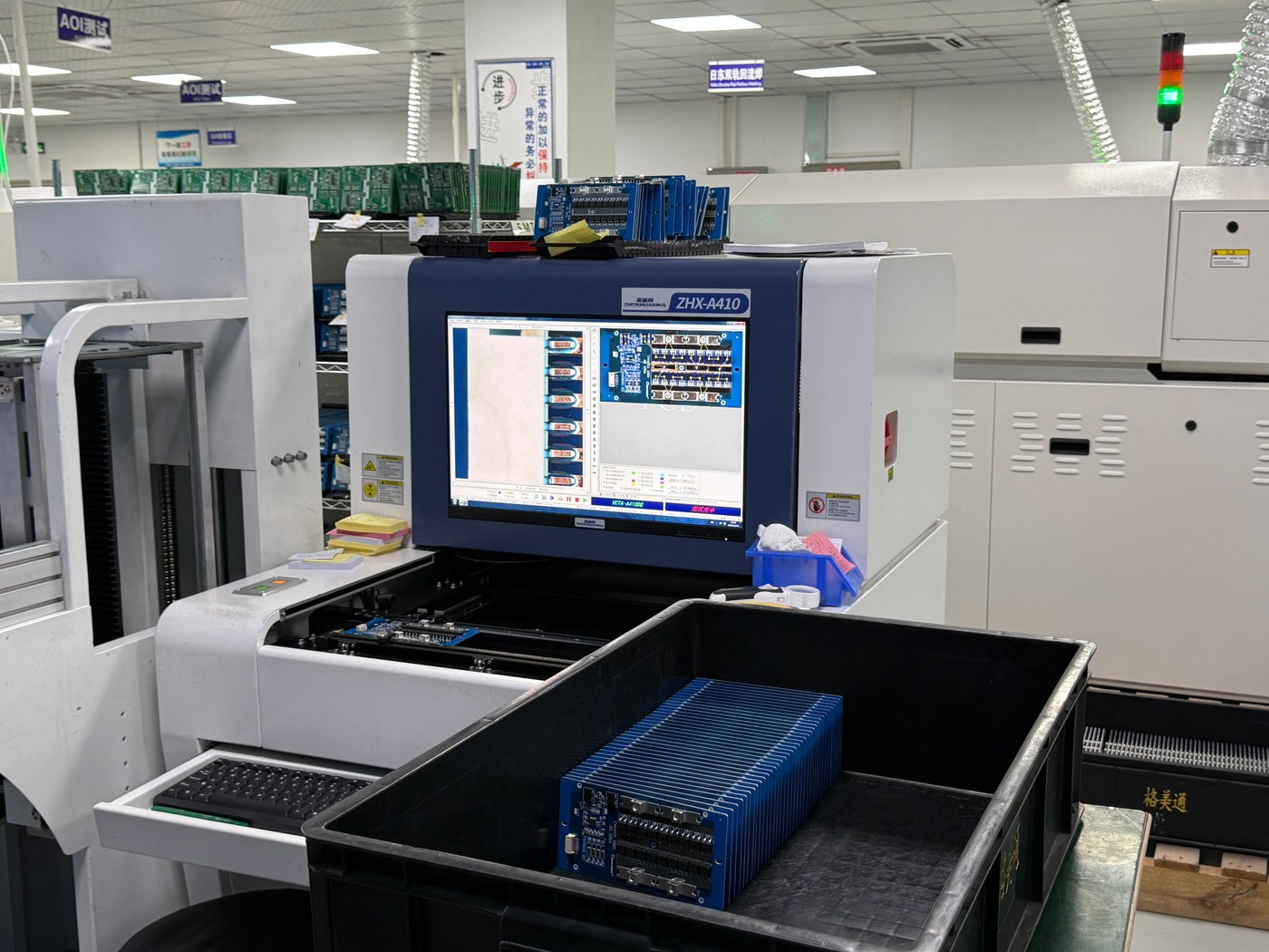
OrinewPCB’s official video below discusses component variation, manufacturability, and first-article checks during the transition from prototype to batch production. For a smart lock, those checks need the specific power and operating-state assumptions developed here.
The full-turnkey PCB assembly scope provides a commercial starting point. For a complete project, provide the controlled build files and power-test requirements, including fabrication data, BOM, placement files, quantities, firmware identity, approved substitutions, and fixture responsibilities, so manufacturing and requested verification can be reviewed against the same release.
Technical sources accessed October 21, 2026. Apply current component documentation and product-owner-approved limits to the actual board. Board-level power evidence does not establish finished-lock security, compliance, or safety approval.
Latest Blog
Contact Info
Phone: +86-755-82882936
Email: [email protected]
WhatsApp: +86-13570802455
Wechat: +86-13570802455
Address: 2nd floor,D Bldg.,Electric Link Technology Bldg.,Gongming,Guangming New Dist.,518106 Shenzhen, China