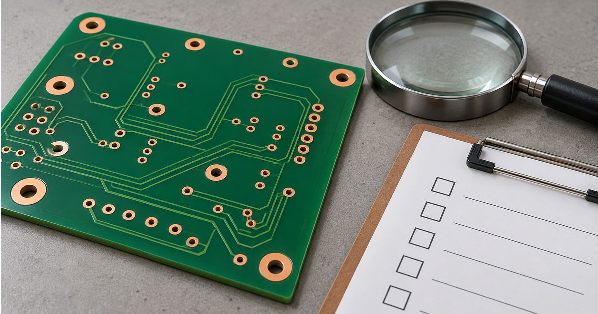
A PCB DFM report is a structured review of design features that may prevent a board from being fabricated, assembled, inspected, or tested as released. The right response is not to approve every suggested change.
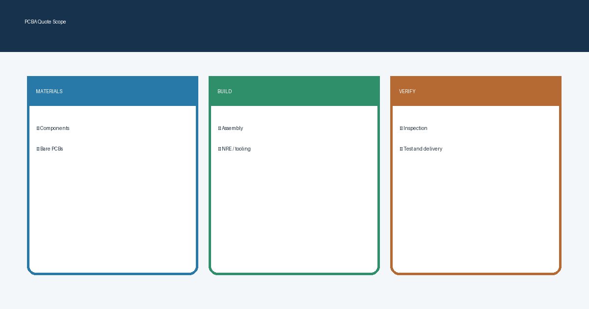
A PCBA quote should separate component cost, bare-board fabrication, assembly labor, setup or non-recurring engineering (NRE), testing, and logistics. That separation lets a buyer compare suppliers on the same scope instead of choosing a deceptively
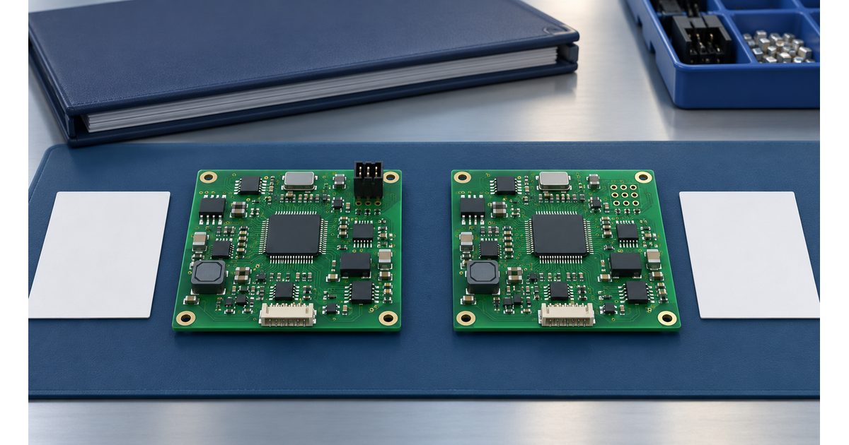
A PCB assembly variant is a defined population of a board design: certain components are fitted, omitted, or changed to create a particular product configuration. The manufacturing risk is not simply forgetting one resistor. It
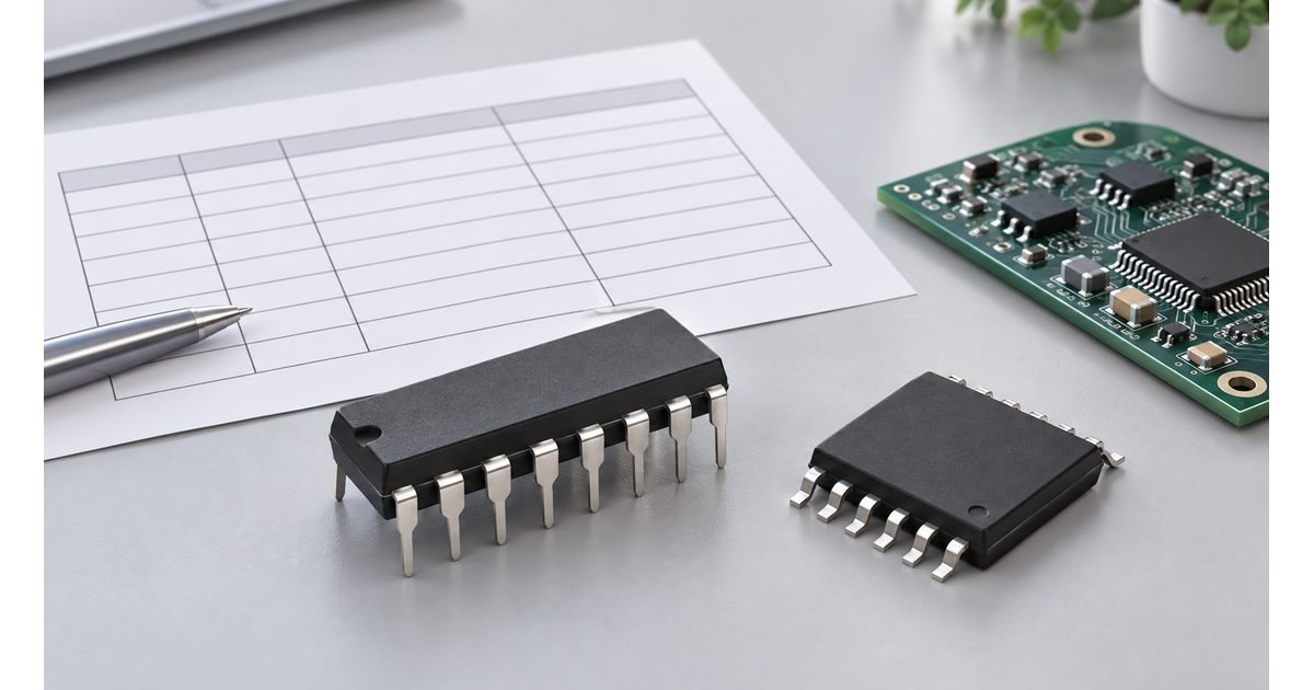
A BOM alternate is not approved simply because a distributor suggests it or an engineer adds it to a spreadsheet. Approval needs an exact device identity, a comparison against the circuit and assembly requirements, appropriate
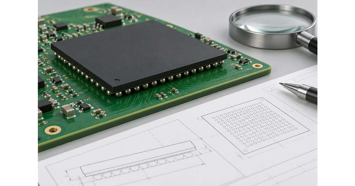
BGA head-in-pillow is an incompletely joined interface between a package solder sphere and the solder deposited on the PCB. The two bodies can reflow without merging into the intended joint. Because the connection lies beneath
Unintended solder balls and beads are separate solder deposits left outside the intended joints on an assembly. They deserve more than a cosmetic judgment: their location, attachment, and potential movement can matter to the product.
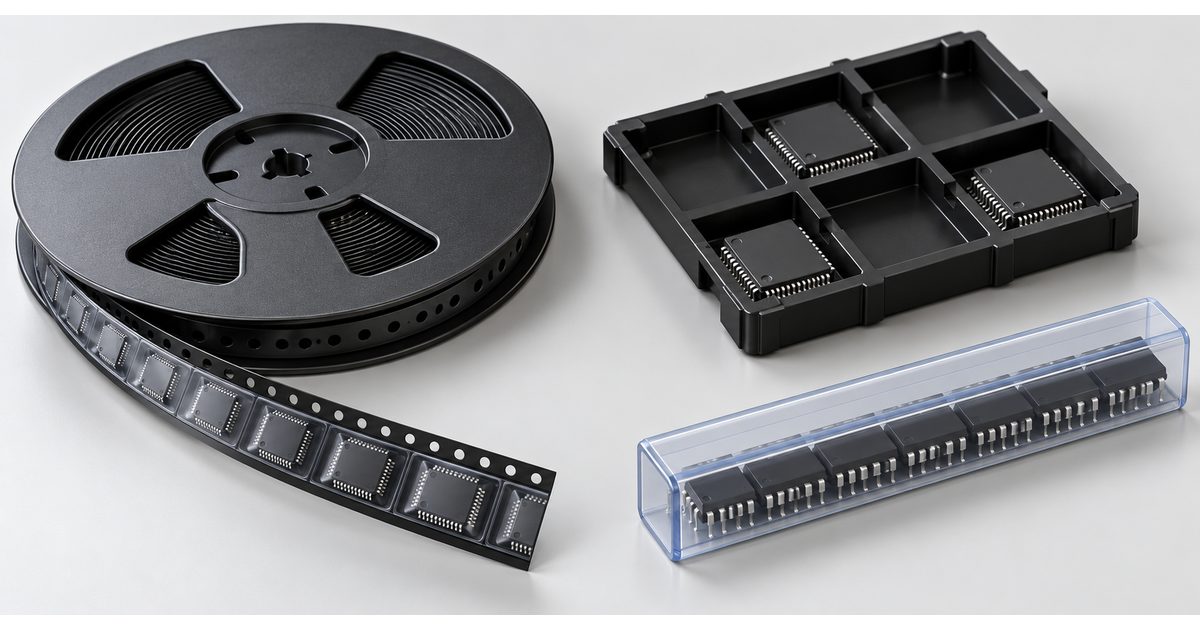
Component packaging affects how parts reach the assembly machine, how their identity is preserved, and how much preparation a production kit needs. Tape-and-reel, cut tape, trays, and tubes describe delivery carriers. They are different from
-
SMT tombstoning occurs when one end of a component lifts away from its intended solder connection during reflow. A small two-terminal passive may stand upright or tilt sharply, leaving an open connection. The visible defect
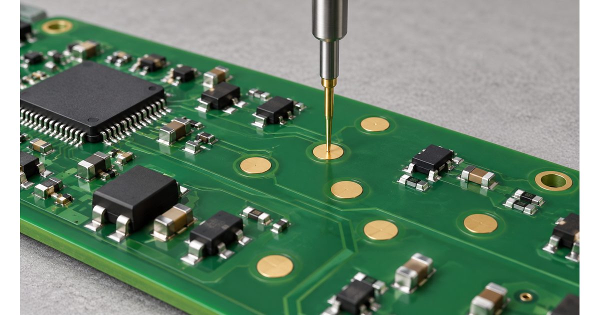
PCB test point design gives test equipment a practical way to contact selected circuit nodes. A useful test point must be electrically appropriate, physically reachable at the required production stage, and clearly identified in the
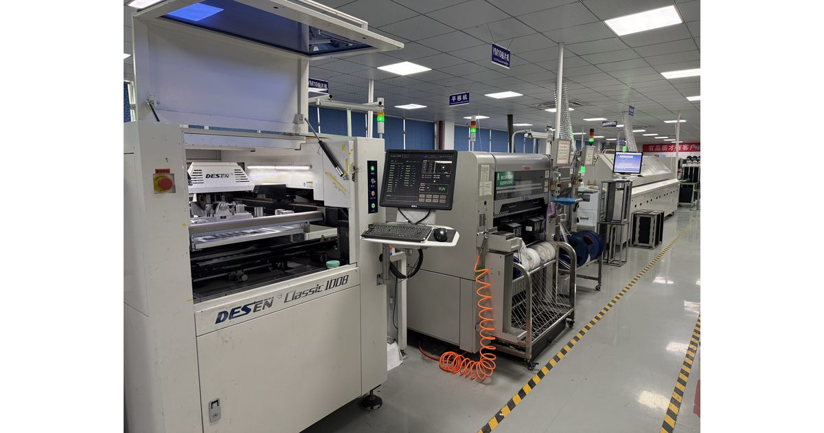
A pick-and-place file tells the assembly team where components belong, which side of the board they occupy, and how they are oriented. It is also called a placement, position, or centroid file. The file supports
Email us for a Free Quote: [email protected]
PCB MANUFACTURING & ASSEMBLY
Start your next PCB project
Share your requirements for PCB fabrication, assembly or component sourcing.

PCB fabrication, assembly and component sourcing — from prototype to production.
Orinew Technology Development Co., LTD.
Contact our team
Address17th Floor, 2B Bldg., Creative Bldg., Time Valley, Heshuikou Community, Matian Street, Guangming Dist., 518106 Shenzhen, China© 2012–2026 Orinew Technology Development Co., LTD.