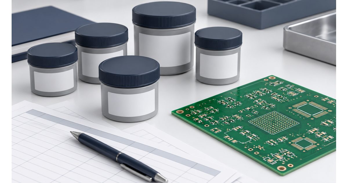
Solder paste storage and handling should preserve both the material and the evidence that it remains suitable for the planned assembly. A jar with the correct alloy can still have an unclear storage, opening, or
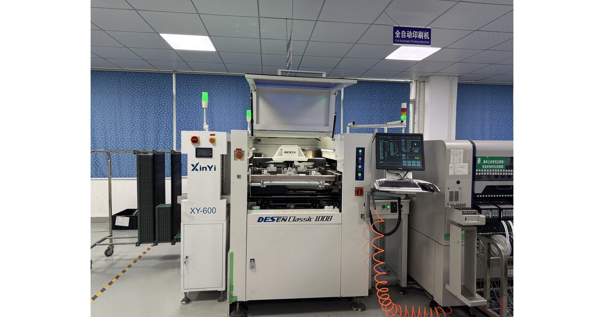
Solder paste inspection, or SPI, evaluates the printed deposits before component placement and reflow. Its value is not just finding a board that needs review. Useful inspection data helps the engineering team understand whether a
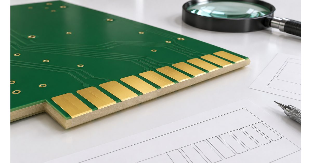
PCB gold-finger beveling shapes the leading edge of a card so it can enter its mating connector with the intended mechanical interface. The gold contacts, board thickness, bevel, and connector geometry must work together. Specifying
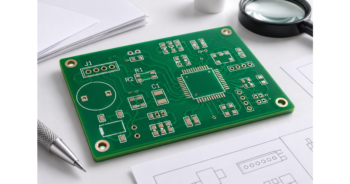
PCB silkscreen design should make the finished board easier to assemble, inspect, connect, and service. A reference designator that looks clear in the layout editor may become incomplete after manufacturing cleanup or disappear beneath a
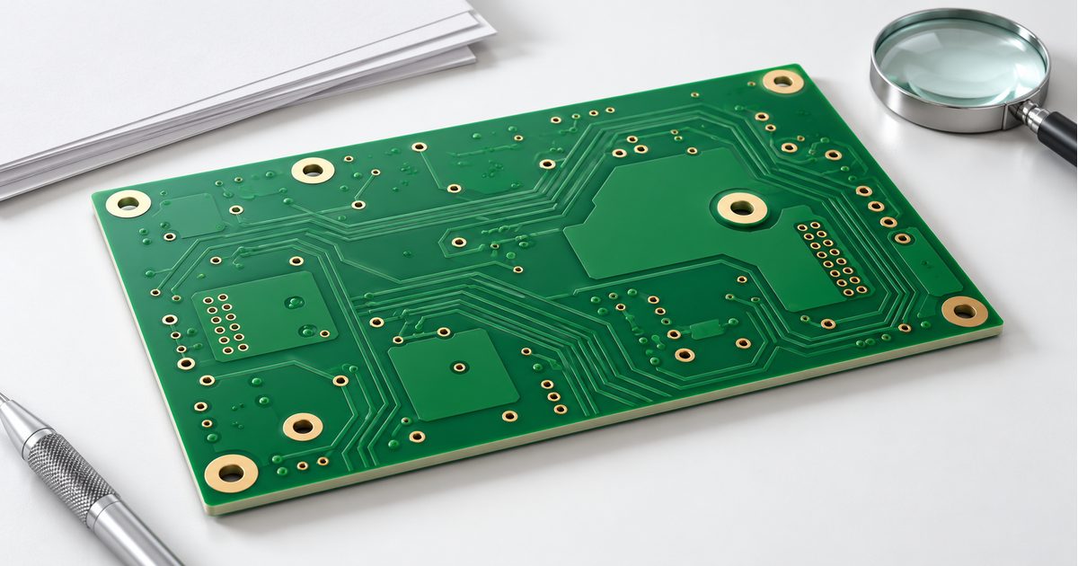
PCB via tenting uses solder mask to bridge a via opening instead of deliberately exposing it. For an ordinary routing via, that can help keep nearby soldering areas separate from an unwanted opening. However, a
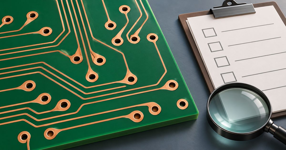
PCB teardrops add copper at the junction where a narrow trace meets a pad, via, or another copper feature. The transition widens gradually instead of leaving the entire connection concentrated at a narrow entry point.
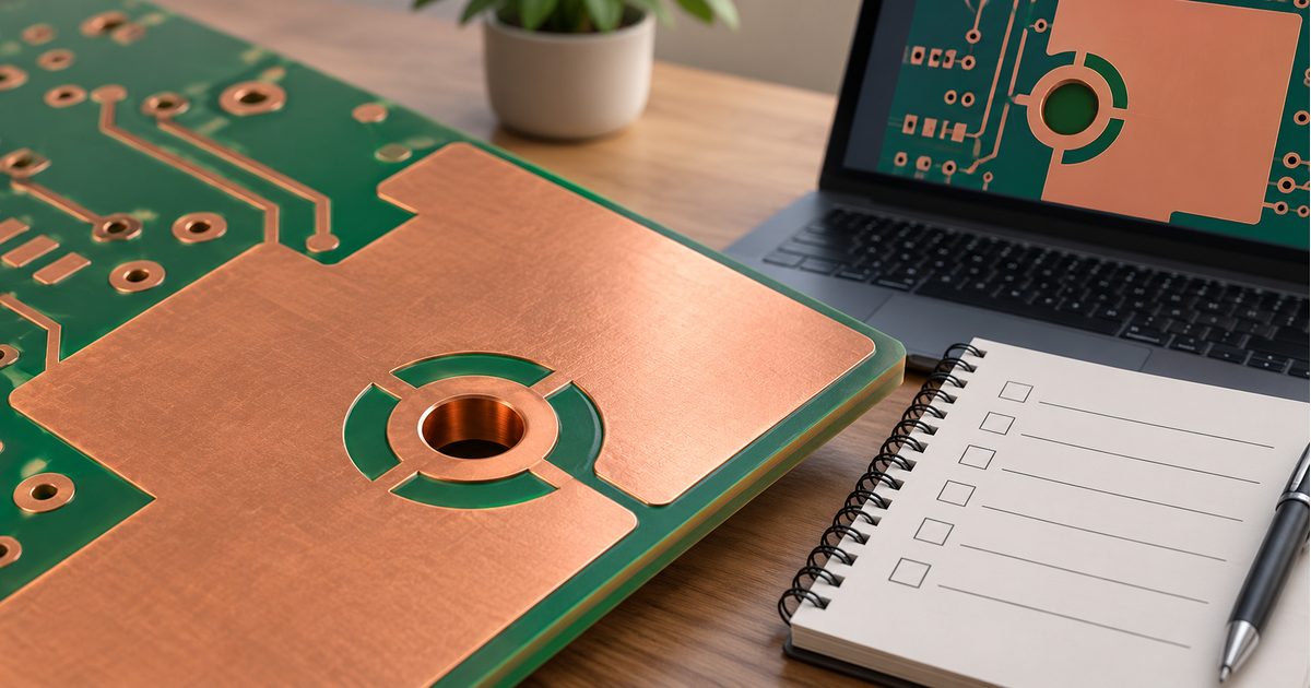
A PCB copper pour creates a copper region around the layout's other features. It can support a defined electrical connection, but filling empty space with copper does not automatically produce a useful ground or power
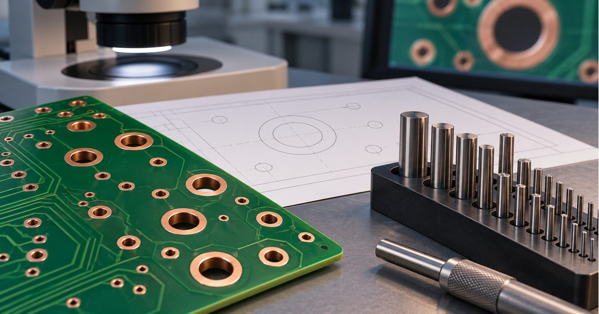
PCB drill tolerances affect whether a component lead enters its hole, a connector pattern aligns, or a board mounts correctly in an enclosure. A nominal hole diameter is only the starting point. The finished opening,
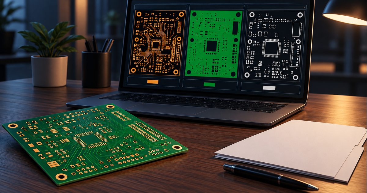
Gerber X2 adds standardized attributes to PCB fabrication artwork. Those attributes help communicate what a file or feature represents, rather than leaving the receiving team to infer its role from geometry and filenames alone. The
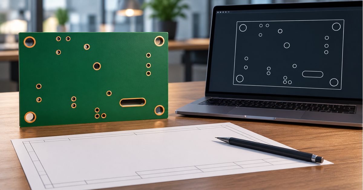
Excellon drill files communicate PCB hole locations and sizes to a fabricator's CAM workflow. They belong in the fabrication package alongside copper artwork, the board outline, and construction requirements. A drill file is not simply
Email us for a Free Quote: [email protected]
PCB MANUFACTURING & ASSEMBLY
Start your next PCB project
Share your requirements for PCB fabrication, assembly or component sourcing.

PCB fabrication, assembly and component sourcing — from prototype to production.
Orinew Technology Development Co., LTD.
Contact our team
Address17th Floor, 2B Bldg., Creative Bldg., Time Valley, Heshuikou Community, Matian Street, Guangming Dist., 518106 Shenzhen, China© 2012–2026 Orinew Technology Development Co., LTD.