
Carton Sealer Controller PCBA: Qualify Prototype-to-Production Changes
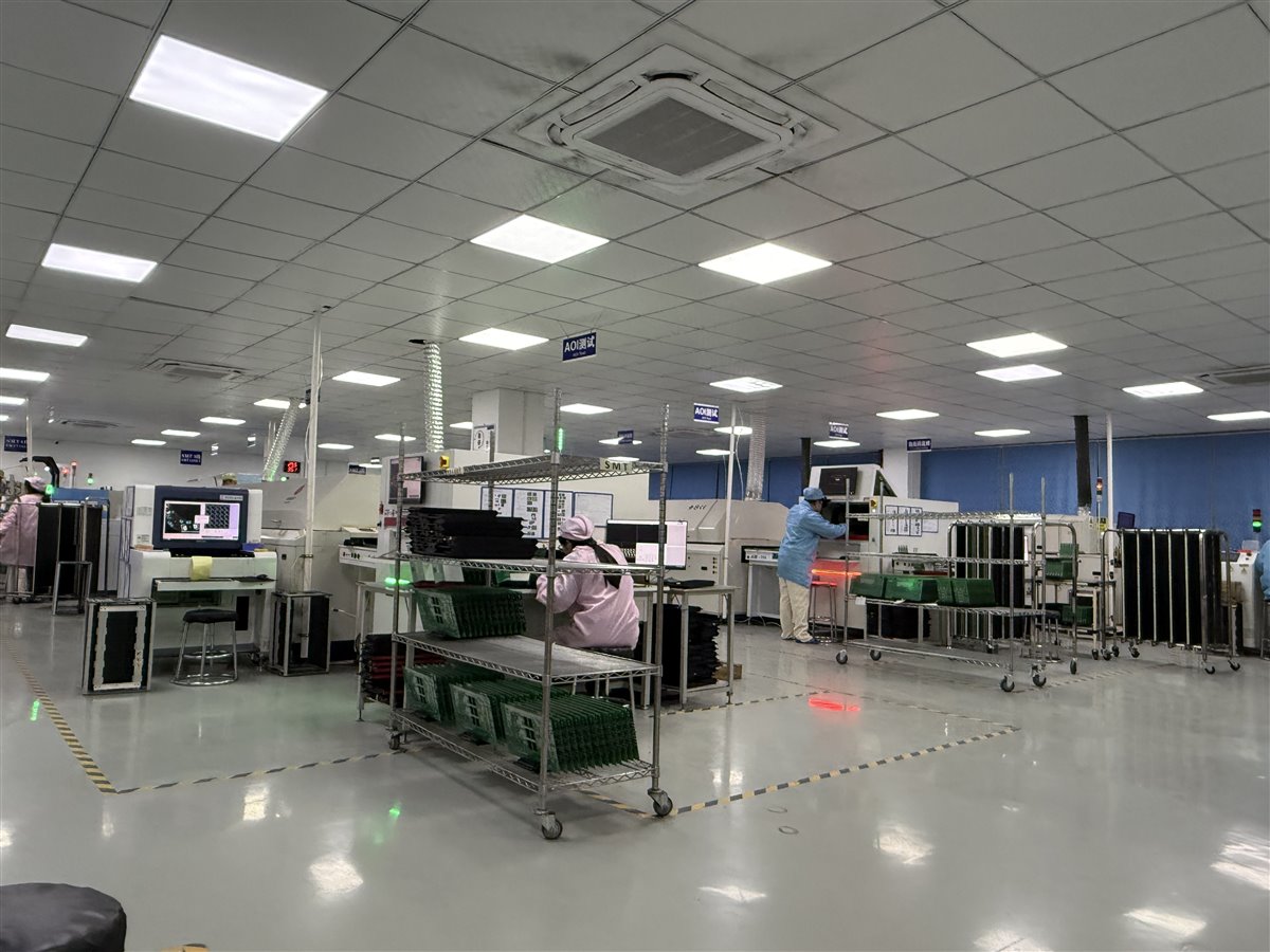
Table of Conent
Table of Conent
A working carton sealer controller prototype is ready for repeatable PCB assembly only when its board revision, approved component set, programmed firmware, fixture, and acceptance limits describe the same machine configuration. Before scaling, freeze those five items, build a pilot lot under the intended process, and confirm that test failures can be traced to the affected units. A powered-on board alone does not establish that a sensor input, servo interface, or interlock will behave consistently after sourcing or process changes.
This guide is for packaging-equipment engineers and buyers moving a controller PCBA from bench build to a qualified production order. The exact I/O and safety architecture depend on the machine: a board may command an external servo drive, contain part of a drive, or only handle sensing and sequencing. The release package and test plan must identify which function belongs to the PCBA and which belongs to the completed machine.
The short OrinewPCB video below explains why a working prototype may still expose component, manufacturability, and pre-production quality risks in a larger PCBA lot. Use it as context for the release gates that follow, rather than as evidence of a carton sealer design.
What must the prototype prove before a pilot build?
Start with a configuration baseline, not a quantity target. Record the PCB and assembly drawing revisions, BOM with approved manufacturer part numbers, programmed firmware and parameter checksum, cable and connector pinout, and the fixture revision used to test the prototype. If a servo drive is external, define the controller-to-drive command, feedback, fault, and enable interfaces. If an encoder connects to the board, document its electrical standard and cable arrangement; industrial encoder interfaces can be sensitive to electromagnetic noise and common-mode disturbances, as Texas Instruments explains for motor-position links.
Separate board-level pass criteria from machine-level validation. A fixture can exercise inputs, outputs, communication, and fault indication, while a final-machine test checks the complete motion, guarding, tape application, and carton path. Do not claim a PCBA test proves a safety function unless the OEM has defined the full system architecture, test method, and applicable requirements.
Before the pilot, review placement orientation, connector access, test points, programming method, and any through-hole or mechanically stressed components. An assembly drawing with controlled polarity and special instructions prevents a correct BOM from being built to an obsolete visual reference.
Which changes require a new approval?
Treat an alternate as a proposed configuration change until the affected function has been reviewed. Form, fit, and nominal value alone may not establish equivalence. For this application, compare sensor-input thresholds and filtering, relay or output ratings, connector keying, power-supply behavior, communication timing, and the interface to the selected servo drive. A changed encoder transceiver or cable termination deserves a focused signal-integrity and fault-response check.
The same discipline applies to firmware. Link every shipped assembly to its programmed image and parameter set; do not let a purchasing substitution, firmware change, and fixture update enter the pilot in one untraceable bundle. Our PCB assembly variant control guide shows how do-not-populate and alternate populations need explicit release data.
| Gate | Evidence to freeze | What blocks release | Decision |
|---|---|---|---|
| Prototype exit | Revisioned files, I/O map, programmed image, known limitations | Unrecorded rework or missing interface limits | Correct the baseline before quoting a repeat build |
| Pilot build | Approved BOM and alternates, assembly process, fixture revision, measured results | Different parts or firmware without targeted revalidation | Hold the affected lot and repeat the impacted checks |
| Production release | Signed acceptance limits, traceability fields, rework disposition, change owner | Failures cannot be tied to board, lot, or test record | Improve records and containment before volume increase |
The table is a release framework, not a universal test specification. The OEM should set electrical limits and decide who authorizes each deviation. When the prototype file set has gaps, share the controlled BOM and assembly package for a manufacturing review, including proposed alternates, intended pilot quantity, and required board-level tests. That lets fabrication, sourcing, assembly, and test assumptions be evaluated together before a production quotation is fixed.
How should the pilot lot be built and inspected?
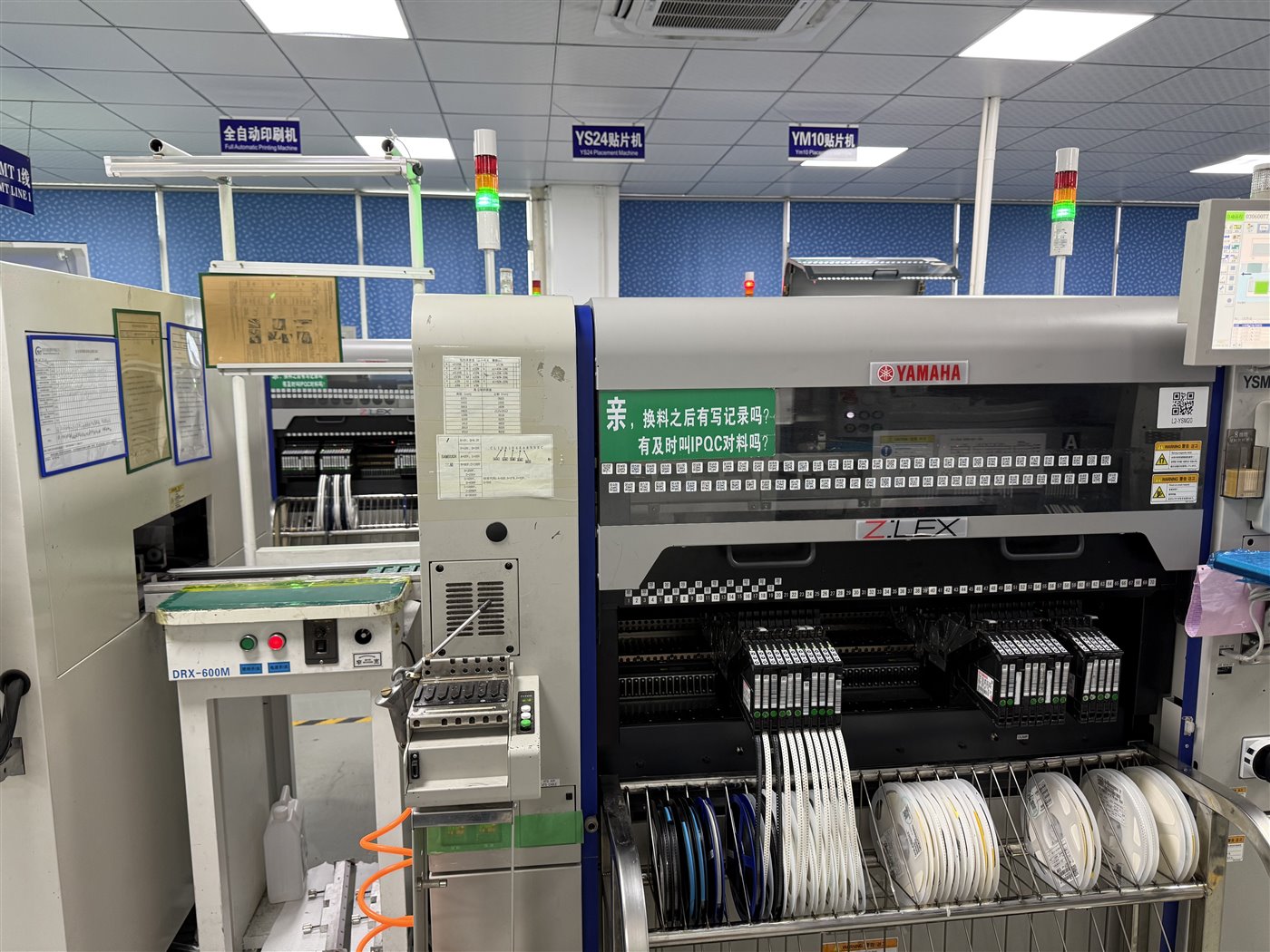
Use the intended production equipment and materials where practical. Record paste, placement program, reflow profile, through-hole operation, inspection criteria, and rework disposition against the actual revision. A hand-built prototype may hide feeder, panel support, or solder-access problems that appear only when the line repeats the operation. The turnkey PCB assembly service scope is relevant when one supplier must coordinate bare boards, sourced parts, assembly, and the agreed test deliverable.
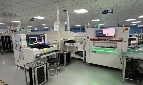
Inspection addresses build quality, but it is not a substitute for functional coverage. IPC distinguishes soldering process requirements in J-STD-001 from post-assembly acceptability in IPC-A-610; the agreed revision and product class belong in the purchase specification, while the OEM still defines the controller’s functional test. See IPC’s explanation of the two standards. Use AOI and other inspection methods according to package visibility and the defects they can actually detect.
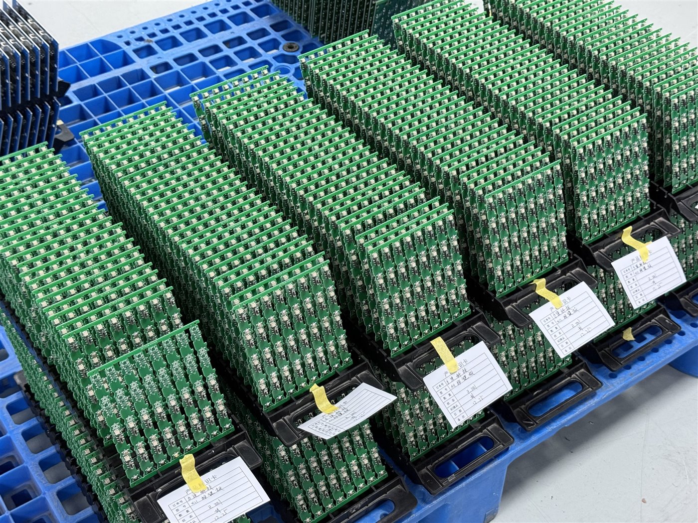
Keep a record that links board serial or lot, bare-board lot, critical component lots where specified, firmware checksum, fixture version, test result, and authorized rework. The depth of traceability should follow the OEM’s risk and contractual requirements. If only a batch identifier is required, make sure it still supports containment when a component or test-limit issue is discovered.
Review the first assembled units against the prototype baseline before releasing the rest of the pilot. Check connector mating, mounting-hole fit, label placement, accessible programming points, and any cable strain at the board edge. These are integration checks, so document which are performed at board acceptance and which wait for the machine build. If the pilot exposes a recurring defect, identify whether it comes from the design data, the supplied component, or the assembly operation before changing a stencil, footprint, or inspection limit. A process adjustment that fixes one lot should be recorded and verified on the next build rather than treated as an undocumented operator instruction.
What should the production functional test cover?
Write the test from the I/O map and the failure modes, not from whatever pins a fixture can conveniently reach. At minimum, decide which rails, digital and analog inputs, outputs, communication ports, programming checks, and fault paths must be exercised on every unit. For servo-related controls, test the commanded interface and feedback or fault reporting that the PCBA actually implements; verify full motion behavior at the machine level when the drive, motor, and guards are installed. Use simulated loads only where they represent the intended electrical conditions.
Include negative cases. An unplugged carton sensor, open interlock input, drive fault, unexpected power cycle, or lost feedback can reveal release risks that a normal operating cycle misses. The expected safe state and acceptance threshold must come from the OEM design and applicable machine requirements; do not infer them from a generic PCBA checklist. A failed unit needs a recorded reason, disposition, and retest path.
For an example pilot, compare fixture outcomes with a limited set of integrated-machine outcomes and investigate disagreements before setting production sampling or coverage. Where access is limited, design test points and connector breakouts into the next revision rather than compensating with an unrepeatable manual probe. The same distinction between a working prototype and a controlled ramp is discussed in our prototype-to-production control-board guide, while the carton sealer I/O and fault cases here remain application specific.
What belongs in the production RFQ package?
Give suppliers one released package: Gerber or ODB++ data, fabrication drawing, stackup and finish, BOM with approved manufacturer parts and substitution rules, CPL or pick-and-place file, assembly drawings, programming files with version controls, planned quantities, panel requirements, and the functional-test specification. State which party supplies fixtures, firmware, consigned parts, cables, and any final-machine test. Ask the quote to separate bare PCB, components, assembly, programming, fixture or nonrecurring work, inspection, functional test, rework assumptions, and shipping scope. That makes pilot and production prices comparable rather than hiding a missing test step inside a unit price.
Quantity should be quoted by stage. A prototype order may carry manual setup and engineering attention; a pilot may add fixture development and evidence collection; production may spread those one-time costs across more units but require additional traceability or incoming-part controls. Compare offers on the same board revision, approved BOM, test time, yield-disposition rule, and delivered scope. A lower unit price is not a saving if the supplier assumes the OEM will program boards, provide the fixture, or diagnose failures after shipment. Record such exclusions explicitly and assign ownership before issuing the purchase order.
A release is ready when a supplier can build the same configuration twice, show what was tested, and isolate affected units after a change. If those conditions are met, provide the revisioned fabrication and assembly files, approved BOM, pilot and production quantities, and test limits with the full build package for scope and quotation review. Engineering can then reconcile PCB fabrication, component sourcing, assembly, programming, and agreed test work against one controlled baseline.
Latest Blog

Contact Info
Phone: +86-755-82882936
Email: [email protected]
WhatsApp: +86-13570802455
Wechat: +86-13570802455
Address: 2nd floor,D Bldg.,Electric Link Technology Bldg.,Gongming,Guangming New Dist.,518106 Shenzhen, China