
Labeling Machine Controller PCB: Release Encoder and Trigger Interfaces
Table of Conent
Table of Conent
A labeling machine controller PCB should be released only after its encoder, product-detect, label-gap, and applicator interfaces have an agreed electrical and timing definition. A schematic shows connectivity; it does not prove that a short sensor pulse survives input filtering or that the firmware counts the intended encoder edges. Before generating Gerbers, connect each interface requirement to a connector pin, circuit, layout constraint, and measurable acceptance test.
This workflow concerns a controller that coordinates label application on a moving product or web. It does not assume that the PCB contains the servo power stage or a thermal printhead. Establish those boundaries first. The useful manufacturing deliverable is a board whose fabrication files, fitted components, firmware configuration, and interface tests describe the same approved machine behavior.
Define what the controller owns before drawing circuits
Assign every function to the controller, external drive, sensor, printer, or machine-level control system. This prevents a PCB from being quoted and tested against responsibilities that belong elsewhere.
Start with the machine sequence: detect a product, measure travel, recognize a label edge, issue an application command, and evaluate the resulting status. Document which events can overlap, which require a fixed response, and what happens during startup, reverse motion, a missing product, or a missing label. A simple I/O list becomes useful when it includes electrical type, active state, pulse duration, receiving device, and expected fault response.
Keep ordinary run and fault signals distinct from any safety-related functions. A general controller input or software interlock does not, by itself, establish a machine safety function. The responsible machine designer must define that architecture and the required validation separately.
The existing label-printer manufacturing handoff guide covers printhead-oriented production transfer. For a conveyor label applicator, the additional release problem is preserving motion and event meaning through the complete input-to-output chain.
Freeze encoder counts and trigger timing as interface requirements
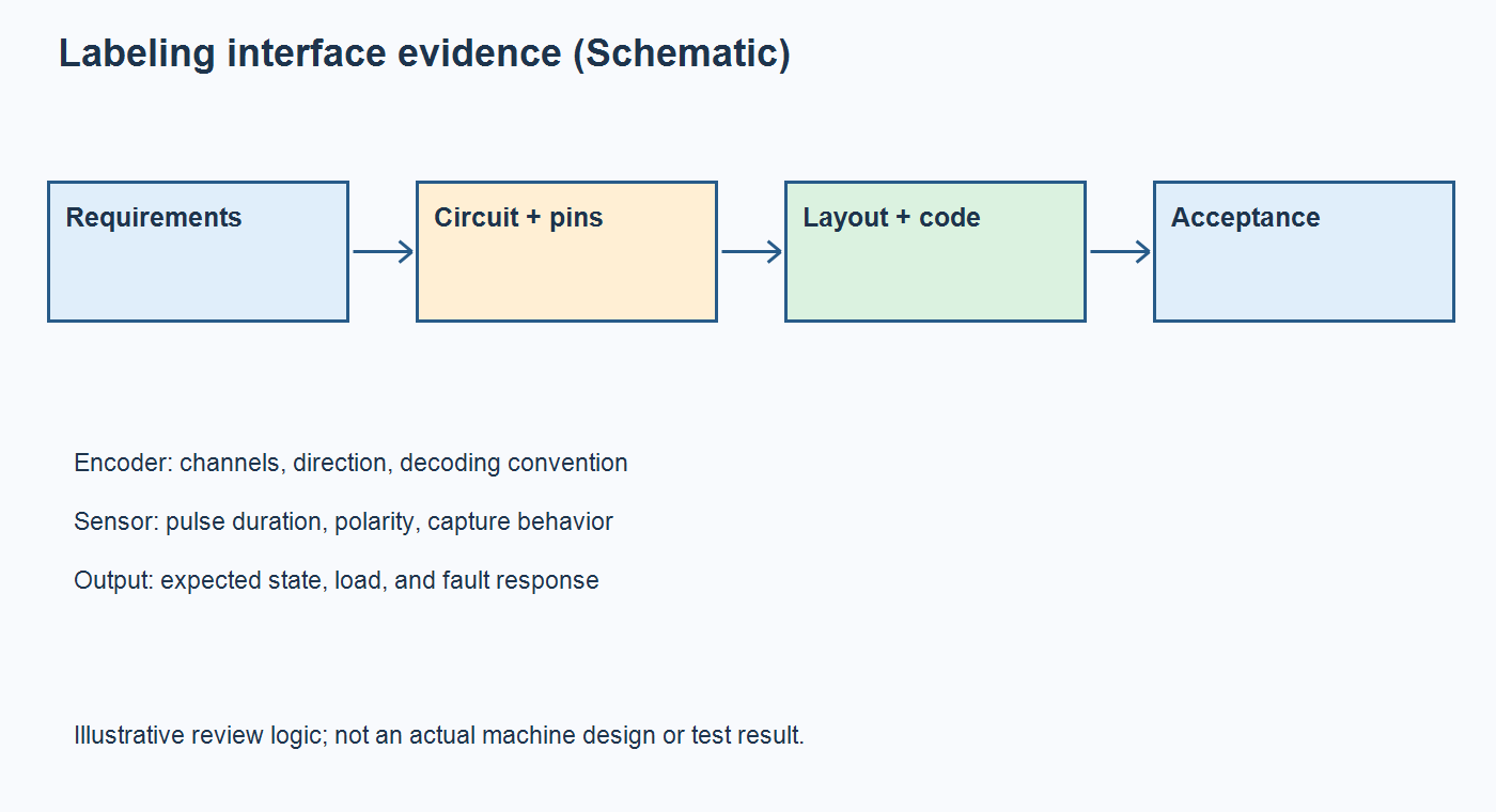
Specify the meaning of a count and the timing of an accepted event before selecting input circuits. Two electrically working boards can behave differently if their decoding mode, polarity, filtering, or reset rules differ.
For an incremental encoder, record the channels actually used, the output electrical type, the direction convention, and the decoding mode. Distinguish encoder cycles from decoded counts: multiplying the count rate through edge decoding also changes the rate the receiving counter must process. If an index is used, define when it may reset or reference position; do not treat every index pulse as an unconditional reset.
For product and label-gap sensors, specify minimum valid pulse duration and spacing, expected inactive state, and whether a sustained active input represents a product, a fault, or an invalid condition. Define the time reference for a trigger: the connector input edge, the conditioned logic edge, or the firmware event. A timing limit is ambiguous unless both measurement points are identified.
As a hypothetical example, a team may find that a noise filter accepts a slow bench signal but rejects the shortest legitimate product-detect pulse. The corrective action is to reconcile the valid-pulse requirement, filtering delay, and capture method, then retest with the released firmware. Increasing the input filter until noise disappears is not a sufficient acceptance criterion.
For differential inputs, evaluate the receiver against the actual signal and installation conditions. The TI AM26LV32E datasheet illustrates why supply range, common-mode range, switching behavior, and the stated open-circuit fail-safe condition must be checked separately. Its specifications do not establish the performance of an entire encoder cable or imply that every shorted-input condition is covered.
Once the interface assumptions are controlled, share the connector map and timing requirements with the build files, including the BOM, placement data, quantity, and proposed stimulus or load models. This lets the engineering review distinguish fabrication, component sourcing, assembly, and test-fixture scope before those assumptions enter a quotation.
Carry the interface definition into placement and routing
Placement should make the intended signal and return paths practical while preserving access for assembly and measurement. A clean schematic cannot compensate for a connector, protection network, or test point that is inaccessible in the finished product.
Review each external signal from its connector through protection and conditioning to its destination. Check the return connection, cable-screen treatment where applicable, power-domain boundaries, and exposure to nearby switching circuits. Termination and filtering belong to a defined interface design; do not copy values from an unrelated reference board without checking the actual driver, receiver, cable, and timing budget.
Place connectors and mounting holes against the mechanical model. Confirm plug insertion space, latch operation, wire exits, enclosure clearances, and tool access. An electrically equivalent connector substitute can still fail the release if its keying, mating height, or cable direction changes. Record approved mating parts instead of asking the assembler to infer them from a connector family name.
Reserve measurement access for signals whose behavior must be verified. Identify whether the fixture measures the external pin, conditioned signal, supply rail, or firmware status. A large test pad is not automatically helpful if the installed connector blocks the probe or its added loading disturbs the signal. Review these access points with the actual test method and fixture owner.
Generate fabrication data from a controlled design state
Export fabrication outputs only after the schematic, PCB database, mechanical interface, and component population agree. Then inspect the exported package independently of the native layout.
Ucamco’s Gerber format description separates layer images and attributes from the job file’s fabrication characteristics. Use that distinction to check both geometry and manufacturing intent: the correct artwork does not replace a defined stackup, finish, or special-process requirement. The separate Gerber X2 release checks explain how attributes support interpretation without proving completeness.
Confirm copper and mask layers, outline, holes, slots, and any required paste data. Inspect drill alignment, plated versus non-plated intent, edge clearances, connector orientation, and revision identity. Compare the exported outline with the mechanical drawing rather than relying on a familiar board shape.
The KiCad 9 PCB Editor documentation provides a concrete example of separate Gerber, drill, placement, and netlist outputs with configurable origins. Whatever CAD tool is used, record the units and coordinate conventions and check the generated artifacts. The assembler should not have to guess whether a bottom-side component was mirrored intentionally.
Use a release-hold table instead of a generic file checklist
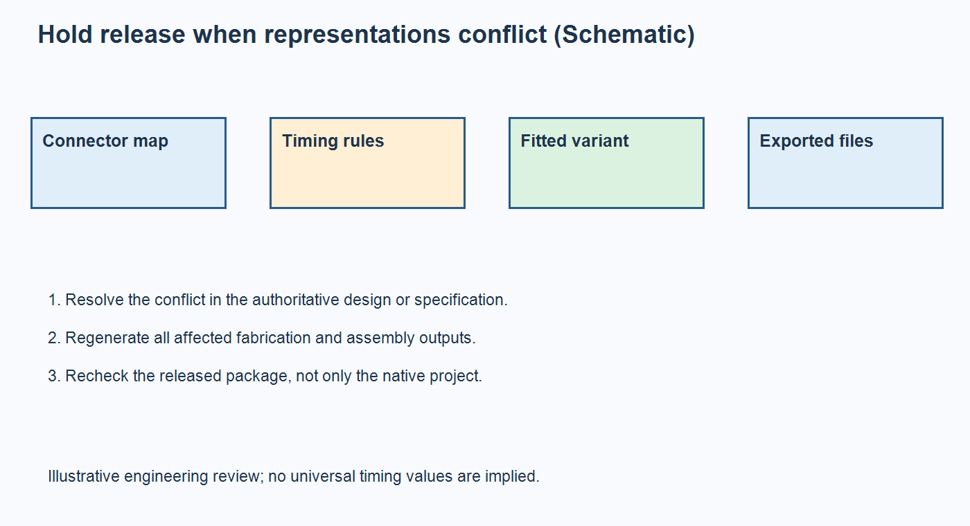
A release should stop when a conflict changes the manufactured board or its accepted behavior. A documented exception needs an owner and an approved disposition, rather than an informal supplier assumption.
| Conflict | Why it matters | Evidence needed before release |
|---|---|---|
| Encoder counts disagree between interface sheet and firmware | Travel or application position can be interpreted incorrectly. | Agreed decoding convention and direction test using the released configuration. |
| Sensor pulse can be shorter than the accepted input response | A valid product or gap event may be missed. | Defined pulse limits and measured end-to-end capture behavior. |
| Connector pinout differs between schematic, harness, and drawing | The PCB can pass isolated checks but fail after installation. | Reconciled pin map, mating part, polarity, and harness revision. |
| BOM variant and placement or assembly drawing disagree | The wrong input option, termination, or output stage can be fitted. | One approved population configuration across all assembly files. |
| Gerber, drill, or outline revisions differ | The physical board may not match the intended connections or enclosure. | Regenerated and independently reviewed fabrication package. |
Use the assembly drawing checklist for the visible build instructions that support these decisions. Keep timing limits in a controlled test or interface specification rather than burying them in a drawing note that the test programmer may never receive.
Separate board acceptance from installed labeling performance
Production testing should prove the defined board interfaces; installed validation must also address the machine, mechanics, cables, sensors, and operating conditions. Passing one does not establish the other.
A board-level fixture can exercise input polarity, encoder direction and counting, trigger capture, output states, communications, programming identity, and defined fault responses. State the stimuli, loads, measurement points, limits, and expected firmware configuration. Decide who supplies the fixture, maintains its software, and approves changes. Inspection methods should address their own defect coverage; the labeling-machine PCBA inspection plan distinguishes visual, hidden-joint, and electrical checks.
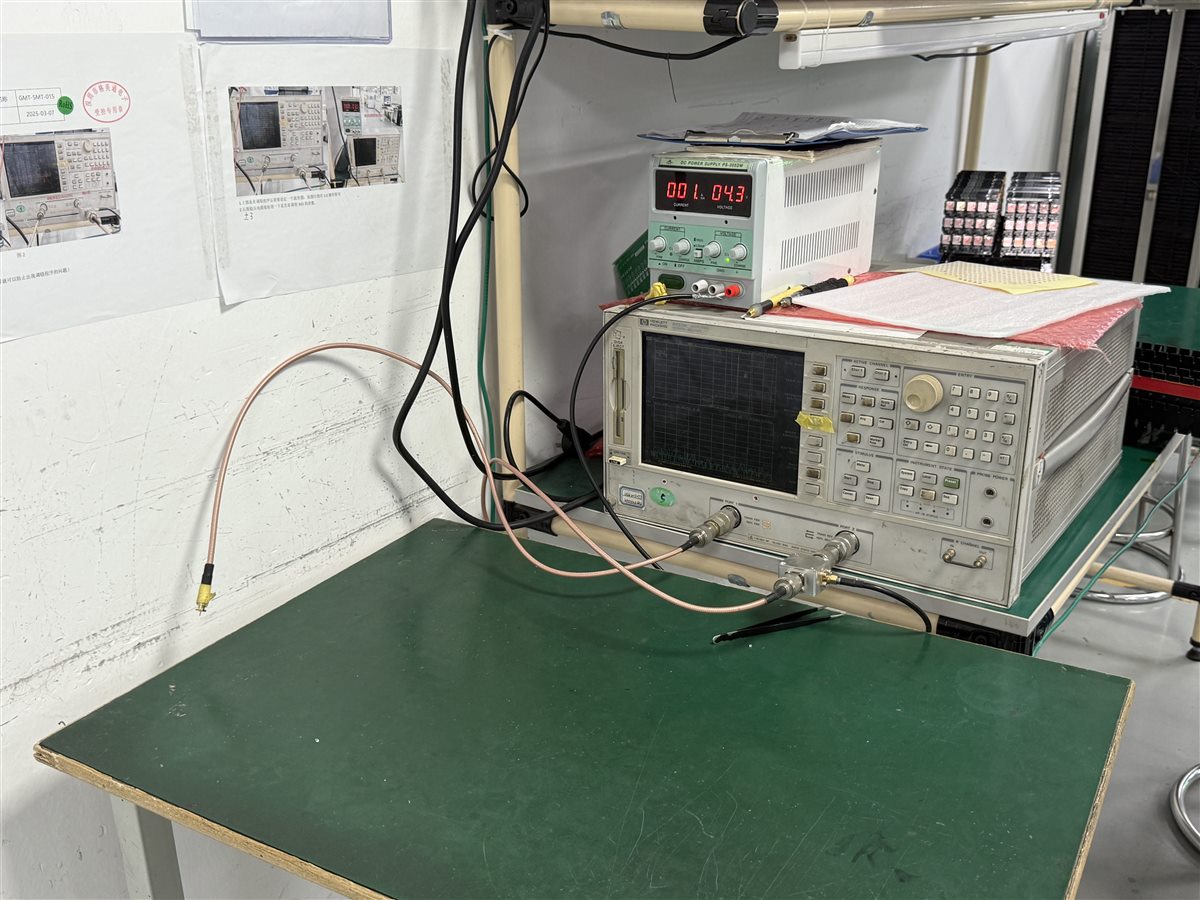
Installed validation should use the actual operating envelope and define acceptable product detection, label sensing, application position, and recovery behavior. A counter test at the PCB connector cannot reveal every mechanical slip, sensor-position error, or cable disturbance. Keep board defects and system-integration issues distinguishable in the acceptance record.
Release one reviewable package for fabrication and assembly
The final package should link the approved interface sheet, fabrication outputs, assembly population, firmware identity, and acceptance specification under one revision. Keep unresolved items visible and exclude superseded alternatives from the build directory.
The official OrinewPCB video below summarizes quotation inputs such as Gerber layers, drill files, and board outline. It supports the manufacturing handoff; it is not a demonstration of labeling-machine timing validation.
A full-turnkey PCB assembly review can coordinate the fabrication, sourcing, assembly, and testing inputs, subject to the agreed project scope. For a ready design, provide the released assembly package and interface acceptance sheet with quantities, approved substitutions, and fixture responsibilities so engineering can reconcile manufacturability and test assumptions before pricing the build.
Release when the files and the expected behavior agree. If an encoder convention, pulse limit, connector mapping, or population choice remains ambiguous, resolve that specific item first; a successful Gerber export cannot make the decision for the project.
Latest Blog
Contact Info
Phone: +86-755-82882936
Email: [email protected]
WhatsApp: +86-13570802455
Wechat: +86-13570802455
Address: 2nd floor,D Bldg.,Electric Link Technology Bldg.,Gongming,Guangming New Dist.,518106 Shenzhen, China