
Solder Paste Inspection: Measurements, Trends, and Corrective Action
Table of Conent
Table of Conent
Solder paste inspection, or SPI, evaluates the printed deposits before component placement and reflow. Its value is not just finding a board that needs review. Useful inspection data helps the engineering team understand whether a print problem is local, systematic, or developing over time, then verify whether a corrective action actually improves the process.
A pass result is not proof of a finished solder joint, and an alarm is not a root-cause diagnosis. Build the workflow around three separate questions: is the measurement trustworthy, does the deposit meet the agreed requirement, and what process change is supported by the evidence? This guide explains that decision path for SMT engineering and assembly procurement.
Understand what the measurement describes
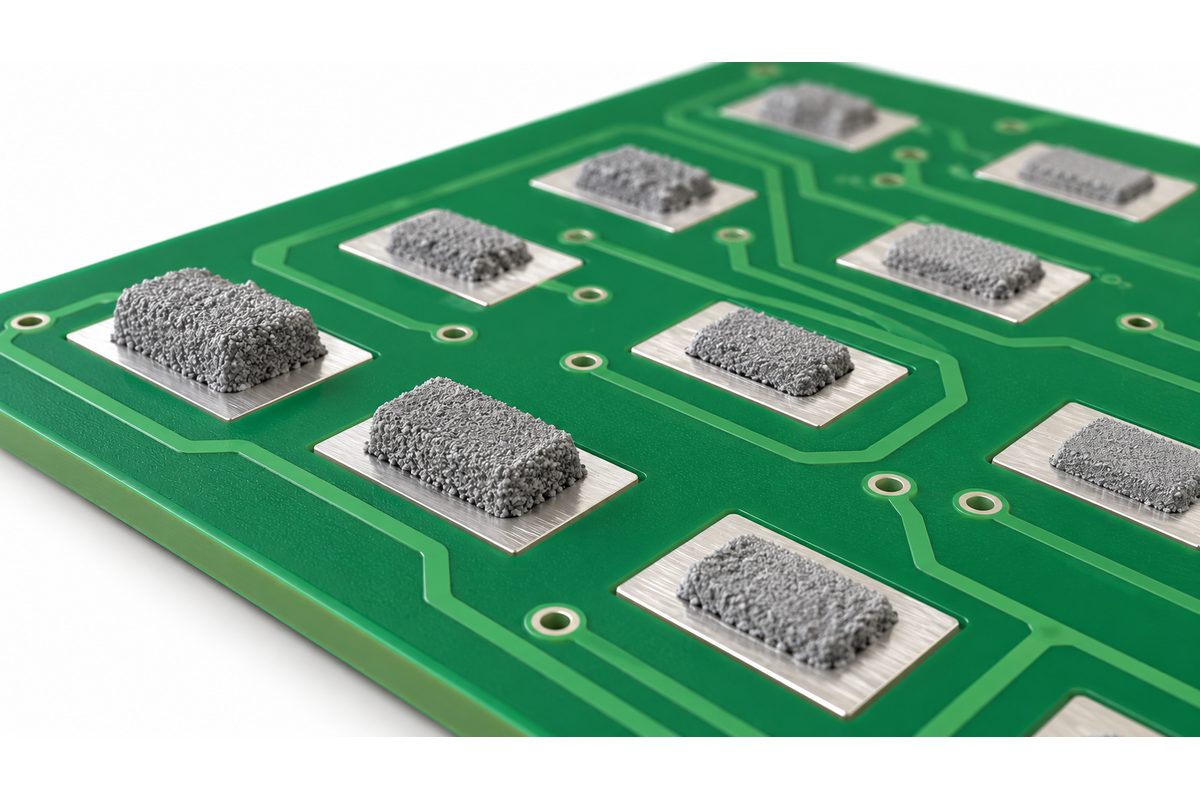
A paste deposit has a location, a footprint, and a three-dimensional shape. Depending on the system and inspection program, relevant outputs can include area, height, volume, and displacement from the intended location. A top-view image alone does not establish the full deposited volume.
Koh Young’s SPI technology overview discusses three-dimensional volume measurement and measurement challenges such as board warpage. Those are inspection considerations, not a guarantee that any machine or program will measure every feature correctly. Review the actual system’s qualified measurement scope.
Distinguish the raw quantity from a percentage reported by the software. A volume percentage depends on its reference definition. Ask whether the reference is based on the stencil aperture, programmed target, or another agreed nominal. Without that definition, comparing percentages from different jobs or suppliers can be misleading.
Establish a controlled printing baseline
Start with matching board, stencil, paste, and inspection-program revisions. Record the aperture data, stencil identity, paste identity and handling requirements, board side, panel arrangement, and intended printing setup. Measurements cannot be interpreted reliably if they refer to a different release than the material being printed.
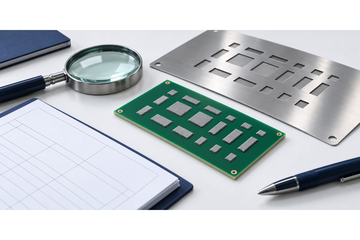
The PCB stencil and printing overview provides context for the relationship between artwork and paste transfer. Keep the target deposit requirements distinct from the copper-pad geometry: a stencil aperture is a process design feature, not automatically a one-to-one copy of every land.
Identify the critical locations for the product. Fine-pitch regions, exposed-pad patterns, and other demanding features may require different attention than large uncomplicated deposits. Group comparisons by meaningful feature type rather than treating every pad on the panel as an interchangeable sample.
Validate the inspection program before interpreting alarms
Confirm that the program locates the board correctly and assigns measurements to the intended deposits. Review the coordinate origin, side convention, fiducial recognition, panel position, and feature definitions. A misplaced measurement region can create an apparent print defect even when the paste is elsewhere as intended.
Check the reference surface and the system’s approach to local board shape. Review repeatability, calibration or verification status, and the measurement behavior on representative features. If the same stationary deposit produces materially inconsistent readings, investigate the measurement setup before adjusting the printer.
Preserve evidence for an alarm: feature identity, image, measured quantities, target definition, program revision, and relevant machine status. A single red indicator without those details is difficult to audit. Avoid disabling a feature simply because it causes repeated calls; determine whether the calls represent a real condition or a program problem.
Planning inspection for a new assembly? send the fabrication files, BOM, placement data, stencil information, and critical paste-inspection requirements for engineering review. Identify the features that need particular attention so the inspection scope can be discussed before quotation.
Use area, height, and volume together
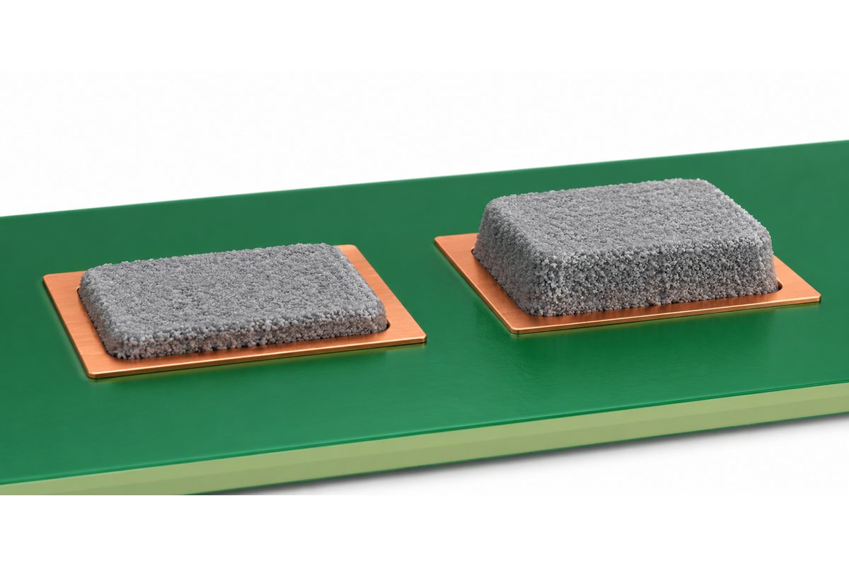
Two deposits can occupy similar plan-view areas while having different heights and volumes. Conversely, a deposit can have a reasonable overall volume while being displaced or shaped in a way that needs review. Do not let one summary metric hide other relevant characteristics.
Read the feature image alongside the values. Determine whether a low-volume call corresponds to a genuinely reduced deposit, an incorrectly defined measurement boundary, or another observable condition. Interpret excessive volume together with location and shape rather than assuming all additional material will be harmless after reflow.
Consider each member of a component’s deposit group, not just the group’s average. A group statistic can conceal one abnormal location. Where balance matters to the assembly process, define how the relevant deposits are compared and what evidence supports the decision, without inventing a universal ratio.
Separate local patterns from board-wide trends
A repeated call at one aperture suggests a different investigation from a common displacement across many features. Look at the distribution by feature, package region, panel position, print sequence, and time. These patterns guide what to examine next; they do not prove a particular cause.
For a localized issue, inspect the corresponding stencil feature and the physical deposit and compare them with the released data. For a broader change, review alignment, board support, material condition, and recorded printing events. Keep competing explanations open until the evidence distinguishes them.
As a hypothetical example, several consecutive panels may show lower measured deposits in one region after a documented process event. Check whether the program, board support, stencil condition, or printing setup changed at that time. Do not immediately revise every aperture or raise every inspection limit. The example illustrates how to organize an investigation, not a diagnosis of an actual production lot.
Define limits from the product and validated process
Do not copy a generic percentage window into every job. Limits should reflect the feature, target definition, measurement capability, and assembly requirements. Document how the limits were established and who can approve a change. Keep review thresholds separate from final product acceptance where the quality plan requires that distinction.
A false call can waste time, but reducing alarms by widening limits is not necessarily process improvement. Record both confirmed print issues and calls caused by measurement or programming problems. Resolve the appropriate problem instead of combining all calls into one unqualified defect count.
Omron’s SPI product documentation illustrates that inspection configurations and analysis tools vary. Equipment availability alone does not establish the qualified inspection coverage for your assembly. Request the proposed program scope and data requirements rather than assuming a model name answers those questions.
Make corrective action a controlled experiment
State the observed condition and the proposed mechanism before changing the process. Select a relevant action, record the starting conditions, and identify what result would support or reject the hypothesis. Where practical, avoid changing several independent settings at once because the result becomes harder to interpret.
Reinspect under comparable conditions and compare the affected features with the original evidence. Check whether the improvement persists across subsequent boards and whether it creates a problem elsewhere. Define containment and disposition for affected material separately from the experiment used to improve the process.
Viscom’s SPI overview describes the use of inspection information in printer and placement feedback. Such integration depends on the actual equipment, configuration, and authorized control workflow. Do not assume every SPI installation automatically changes the printer or that automatic feedback removes the need for engineering verification.
Need to clarify the proposed control plan? submit the assembly package, critical feature list, inspection reporting needs, and proposed corrective-action expectations for a manufacturing and quotation review. State what evidence you need for first articles and repeat builds.
Correlate SPI with downstream results
SPI inspects paste before soldering. Component placement, thermal processing, materials, and other conditions still affect the assembled joint. Link SPI observations with the appropriate placement, optical, X-ray, electrical, or functional evidence required by the product, rather than treating one inspection stage as complete coverage.
The reflow soldering overview addresses that later process stage. When evaluating a suspected paste-related solder defect, preserve the traceability between the printed board, inspection result, component placement, and soldering run. A correlation is a useful lead but still needs a defensible mechanism.
Discuss the relevant inspection and reporting requirements with the SMT assembly service team for the actual job. This is a project-specific scope discussion, not a claim that a particular SPI model, feedback configuration, or numerical detection rate is installed or guaranteed.
Keep reporting definitions explicit
For a supplier report, identify whether a count refers to boards, panels, deposits, alarms, reviewed calls, or confirmed conditions. State the production window, denominator, program revision, and disposition method. Do not compare two percentages until their definitions and inspection coverage match.
Preserve the inspection program and approved changes with the manufacturing revision. A new board layout, stencil revision, paste choice, or package substitution may require another program review. Repeat orders should use the accepted control plan, not an undocumented combination of old targets and new production data.
Pre-release checklist
- Match board, stencil, paste, and inspection-program revisions.
- Define the measured quantities and their nominal references.
- Validate alignment, feature regions, reference surfaces, and repeatability.
- Set limits through the agreed product and process-control plan.
- Investigate spatial and time patterns without declaring an unproven cause.
- Verify corrective actions and connect the evidence to downstream assembly results.
Solder paste inspection is most useful when measurement, acceptance, investigation, and verification remain distinct. Reliable data and controlled decisions give the team a stronger basis for improving printing than a pass count or an unexplained alarm alone.
Ready to plan the build? submit the final assembly files, quantities, stencil requirements, critical locations, and inspection deliverables for engineering review and quotation. Resolve the reporting and acceptance scope before production starts.
Latest Blog

Contact Info
Phone: +86-755-82882936
Email: [email protected]
WhatsApp: +86-13570802455
Wechat: +86-13570802455
Address: 2nd floor,D Bldg.,Electric Link Technology Bldg.,Gongming,Guangming New Dist.,518106 Shenzhen, China