
Shrink-Wrap Machine PCBA: Sequence SMT, Reflow and Through-Hole Assembly
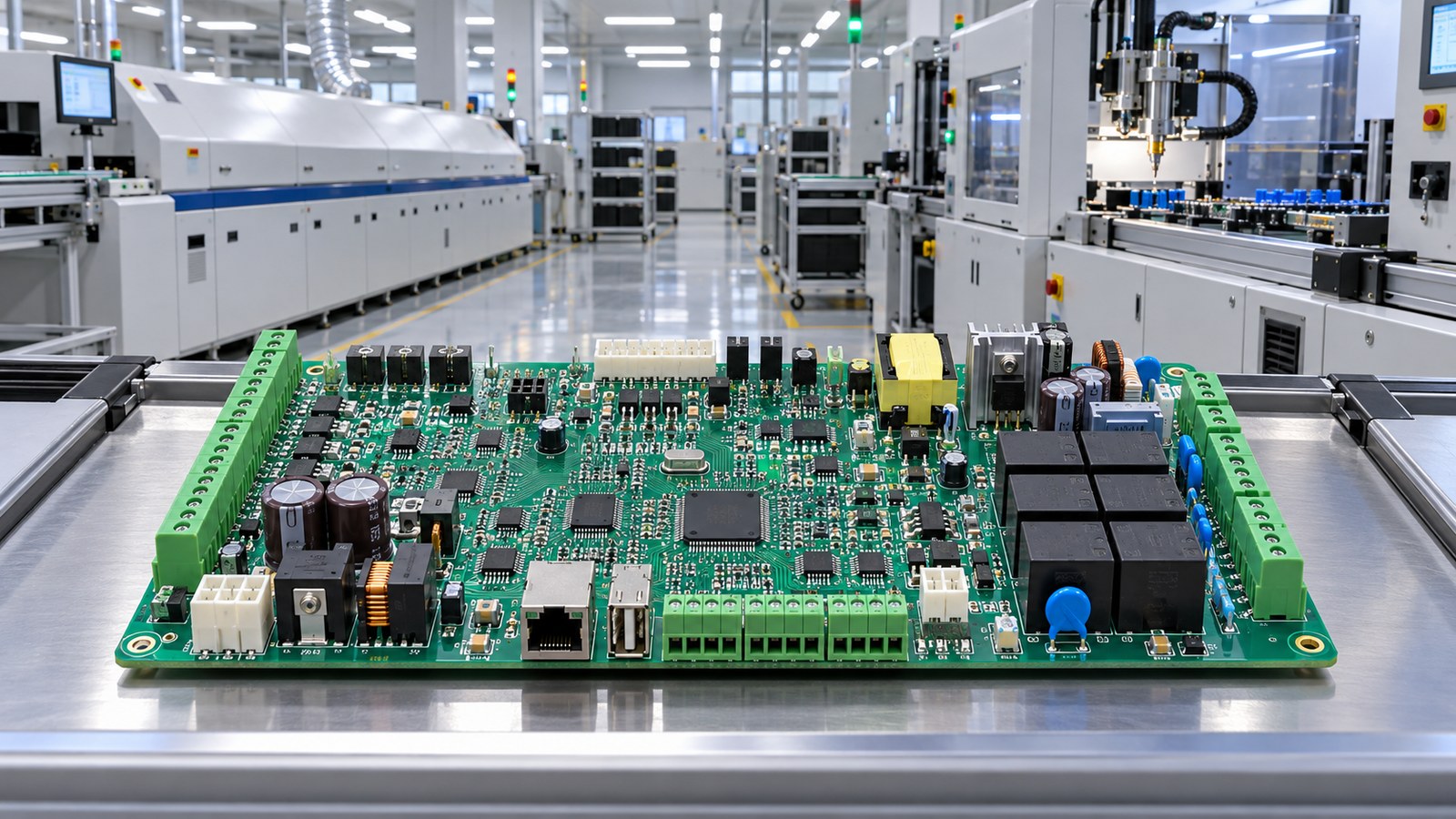
Table of Conent
Table of Conent
A shrink-wrap machine controller is rarely an all-SMT board. The logic, sensing, and communications sections may use fine-pitch surface-mount parts, while heaters, motors, solenoids, safety circuits, and field wiring require relays, large connectors, transformers, and other through-hole hardware. That mix is normal. The manufacturing risk appears when the process sequence is treated as a collection of independent steps instead of one controlled thermal and mechanical flow.
A robust build plan starts with the board’s actual component population, solder-joint access, thermal mass, and test strategy. For most conventional mixed-technology assemblies, the defensible baseline is SMT printing and placement, reflow, inspection, through-hole insertion, then a controlled secondary soldering process. Pin-in-paste can consolidate selected joints into reflow, but it is a design-specific option rather than a universal shortcut. The sequence should be selected from evidence, documented in the traveler, and validated on production-representative assemblies.
Why shrink-wrap controllers create a mixed-technology challenge
Shrink-wrap equipment combines precise motion with substantial electrical loads. A controller may coordinate an infeed conveyor, photoelectric sensors, servo axes, film feed, sealing jaws, a heat tunnel, emergency-stop circuits, and operator-panel communications. The PCB therefore places low-voltage digital circuitry near switching devices and field connectors that must survive vibration, current, cable forces, and repeated service.
SMT supports compact control electronics and automated placement. Through-hole parts provide useful mechanical retention and accommodate packages that are impractical in SMT form. The difficulty is not simply that two attachment methods exist. Each later operation can change the condition created by an earlier one: a heavy connector can shadow a selective-solder nozzle, a pallet can trap heat, flux can reach a keep-out area, and manual insertion can damage an already-reflowed component. The routing must anticipate these interactions before the first lot enters production.
Start with a component and process map
Classify every component by termination style, peak-temperature tolerance, coplanarity, mass, polarity, mechanical load, moisture sensitivity, and solderability. Then classify every joint by its intended process: reflow, pin-in-paste, selective soldering, wave soldering, hand soldering, or a documented exception. This joint-level map prevents ambiguous instructions such as “solder remaining parts,” which leave critical decisions to the line.
The map should also flag bottom-side SMT parts, nozzles and pallet clearances, tall-component interference, connector seating requirements, and areas that must remain free of flux. If a relay, terminal block, or transformer is heat-sensitive, its supplier limits belong in the routing. If a connector must sit flush to the board to meet enclosure geometry, the insertion and support fixture must make that condition repeatable.
A practical SMT-to-through-hole sequence
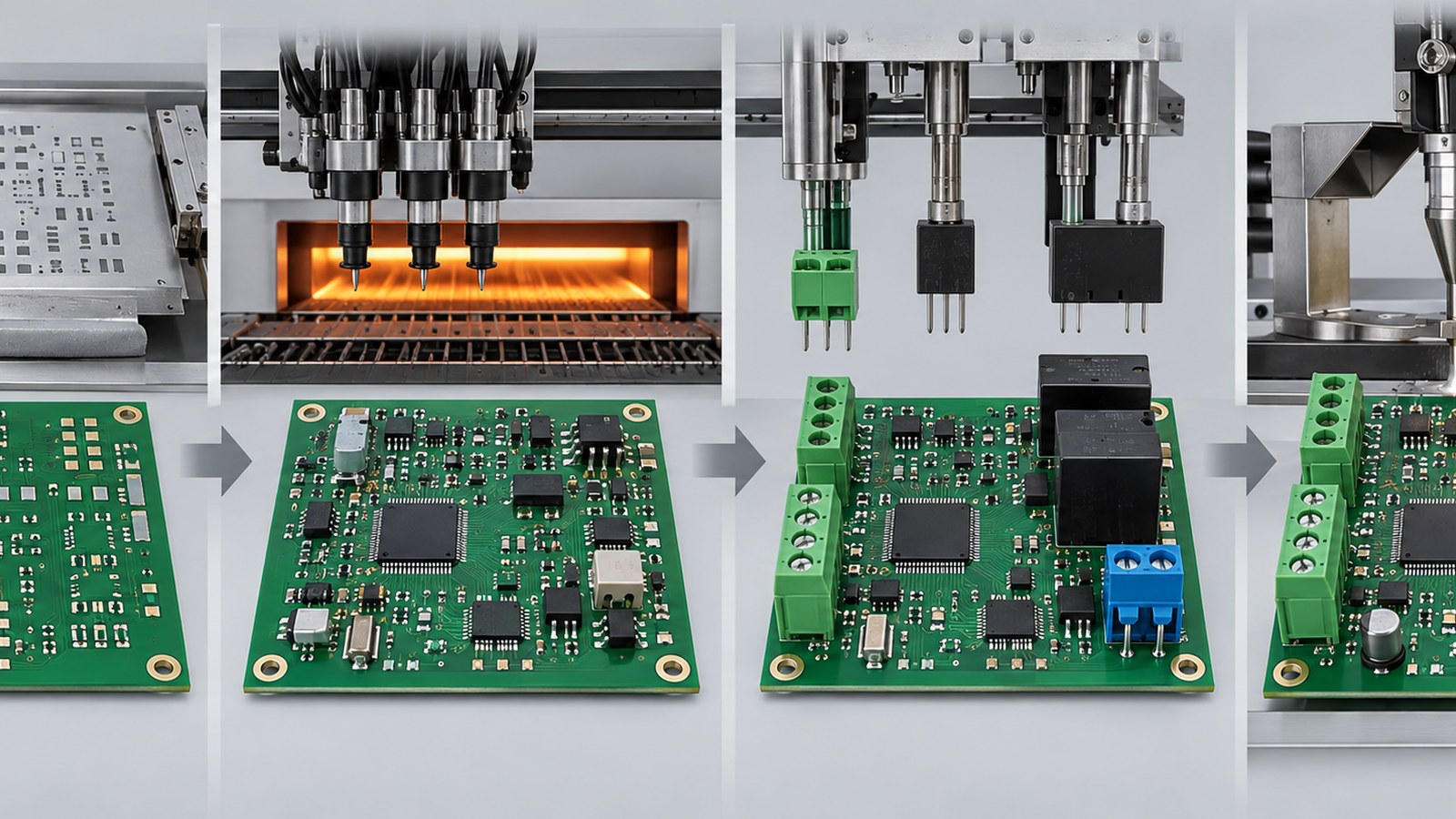
The following sequence is a strong starting point, not a substitute for product-specific process engineering:
- Incoming control and preparation: verify PCB revision, component identity, moisture controls, solder-paste condition, stencil revision, and feeder setup. Confirm that the bill of materials and assembly drawing resolve polarity and approved substitutions.
- Stencil printing and inspection: print solder paste for SMT joints and any approved pin-in-paste locations. Use solder-paste inspection where risk justifies it, and react to trends rather than waiting for visible defects.
- SMT placement and first-side reflow: place components, run the validated profile, and protect the assembly from unnecessary handling after reflow.
- Post-reflow inspection: review polarity, alignment, solder bridges, insufficient joints, tombstoning, and process escapes. Resolve defects before through-hole hardware hides access or adds thermal mass.
- Through-hole insertion: install relays, connectors, transformers, and terminals with controlled seating, lead protrusion, polarity, and mechanical support.
- Secondary soldering: use selective soldering, wave soldering, or controlled hand soldering according to the joint map. Inspect joints and cleanliness, then proceed to programming, electrical test, functional test, and final acceptance.
Temperature profiling is a control plan, not a one-time oven setup. IPC lists IPC-7530B as the current published guideline for temperature profiling of mass-soldering processes. A useful profile represents the actual product, including dense copper, large inductors, shields, and other heat sinks. The relevant evidence includes component-temperature limits, solder-alloy requirements, time above liquidus, ramp rates, and thermal differences across the assembly.
Choose the secondary soldering method by access and risk
Selective soldering is often appropriate when only a limited set of through-hole joints remains after reflow. It can localize flux and heat, avoid immersing sensitive areas, and provide programmable control over individual joint groups. Indium’s overview of selective soldering applications describes the method’s fit for assemblies that cannot be processed safely by conventional wave soldering. Nozzle access, board support, lead length, solderability, dwell, and nearby component clearances still require validation.
Wave soldering can be efficient for a dense population of compatible through-hole parts, especially at volume. It introduces more global heat and flux exposure, however, and may require pallets or masking to protect SMT features. Pallet design must account for shadowing, drainage, board support, and repeatable presentation to the wave.
Hand soldering is useful for prototypes, low-volume exceptions, or joints that automated equipment cannot reach. It should not mean uncontrolled workmanship. Tip geometry, temperature, dwell, flux, solder alloy, operator qualification, and inspection criteria still need documented limits. If repeated manual touch-up becomes normal production, the root cause belongs in design or process engineering.
Our guide to selective soldering joint maps and verification explains how access and acceptance evidence should be connected. For a new shrink-wrap controller, the contract manufacturer should be able to explain which joints use each method and why. If you want that sequence reviewed before release, send the BOM, Gerbers, assembly drawings, expected volume, and special connector requirements through our PCB assembly inquiry form. We can identify process conflicts before they become recurring rework.
Use pin-in-paste selectively, not automatically
Pin-in-paste, also called intrusive reflow, deposits paste at a plated through-hole so a compatible leaded component can solder during SMT reflow. It can eliminate a later operation for suitable connectors and small through-hole parts. Success depends on calculated solder volume, aperture design, hole fill, lead protrusion, component seating, flux behavior, and the component’s reflow-temperature capability.
Large terminal blocks, relays, and high-mass magnetics are not automatically good pin-in-paste candidates. The required paste volume may be impractical, the body may not tolerate reflow, or the joint may need a different process window. Compare the design with our focused discussion of fine-pitch SMT and pin-in-paste balance and the broader technical overview of PIP through-hole reflow technology. The goal is not to maximize the number of joints in reflow; it is to minimize total risk and variation.
Control the interactions that create hidden defects
Thermal mass and profile separation
A power section can lag far behind small logic components during heating. Profiling only an easy location can create a false sense of control. Place thermocouples at likely hot and cold points, attach them in a repeatable manner, and document the load configuration. Our article on thermocouple placement for mixed-mass PCBAs covers this evidence-driven approach.
Mechanical support and connector seating
Heavy through-hole hardware can bow the PCB or shift while solder is molten. Fixtures should support the board without loading fragile components, blocking heat transfer, or trapping flux. Connector seating and perpendicularity should be checked against the enclosure and mating-harness requirements, not only against a generic workmanship photograph.
Flux, cleanliness, and coating
Secondary soldering adds another flux event. Define whether residues are acceptable for the electrical environment, coating system, humidity exposure, and test method. Areas intended for conformal coating must be clean enough to support adhesion and electrical reliability. Conversely, connectors, test points, adjustment devices, and keep-out features may need masking before coating.
Rework limits
Every extra heat cycle consumes process margin. Establish limits for touch-up, pad and barrel condition, component reuse, cleaning, and escalation. Repeated bridges, insufficient hole fill, or lifted pads should trigger root-cause review rather than routine cosmetic repair. The latest J revisions of the widely used assembly requirements were announced by IPC in its release covering J-STD-001J and IPC-A-610J; the specific product class and acceptance criteria must be agreed in the build documentation.
Inspection must follow the risk, not just the process name
SMT inspection may combine automated optical inspection, X-ray for hidden joints, and targeted visual review. Through-hole inspection should address wetting, hole fill, lead protrusion, solder bridges, connector seating, polarity, and mechanical integrity. Acceptance cannot be inferred from the top side alone when barrels and solder-side fillets carry the evidence.
Electrical testing should verify power rails, shorts, opens, protection circuits, programming, and communications. Functional testing should exercise the controller’s actual interfaces or representative loads: sensors, motor or servo commands, heater outputs, safety interlocks, film-feed controls, and fault reporting. The test specification should define limits and capture traceable results by serial number or lot.
For recurring production, monitor defect data by operation and joint family. If insufficient fill clusters around one high-mass connector, changing the oven profile may be irrelevant when the defect arises in selective soldering. If SMT bridges rise after a stencil change, final test is too late to be the primary control. Process-specific data makes corrective action faster and more defensible.
What to give your contract manufacturer
A complete release package should include fabrication data, Gerbers or ODB++, centroid data, BOM with approved manufacturer part numbers, assembly drawings, schematic where permitted, programming files, test requirements, panel information, and any mechanical constraints. Add the intended solder alloy, cleanliness expectations, conformal-coating requirements, traceability, workmanship class, and special handling notes.
Ask the manufacturer to return a process flow that identifies reflow sides, through-hole insertion points, secondary soldering methods, fixtures, inspection gates, and test stages. This is more useful than a generic capability statement. AssyPCB’s PCB assembly service can support SMT, through-hole, mixed-technology builds, programming, testing, and box-build integration under one manufacturing plan.
Release the sequence only when the evidence closes
Before volume production, confirm that the profile is representative, all joints are assigned to a qualified process, fixtures do not create damage or thermal surprises, inspection criteria are unambiguous, and the functional test detects faults that matter in the machine. First-article data should resolve open questions rather than merely prove that one board powered on.
A shrink-wrap controller PCBA is reliable when SMT and through-hole operations are engineered as one sequence. Reflow creates the electronic foundation; insertion and secondary soldering add the high-load interfaces; inspection and functional test prove that the combined process meets the product requirement. To review a mixed-technology build for manufacturability, send the production files and acceptance needs through our project review form. The resulting quotation can be tied to a defined routing instead of assumptions about how the board will be assembled.
Latest Blog
Contact Info
Phone: +86-755-82882936
Email: [email protected]
WhatsApp: +86-13570802455
Wechat: +86-13570802455
Address: 2nd floor,D Bldg.,Electric Link Technology Bldg.,Gongming,Guangming New Dist.,518106 Shenzhen, China