
LWD Sensor PCB Lead Times: Parts, Materials, and Release Gates

Table of Conent
Table of Conent
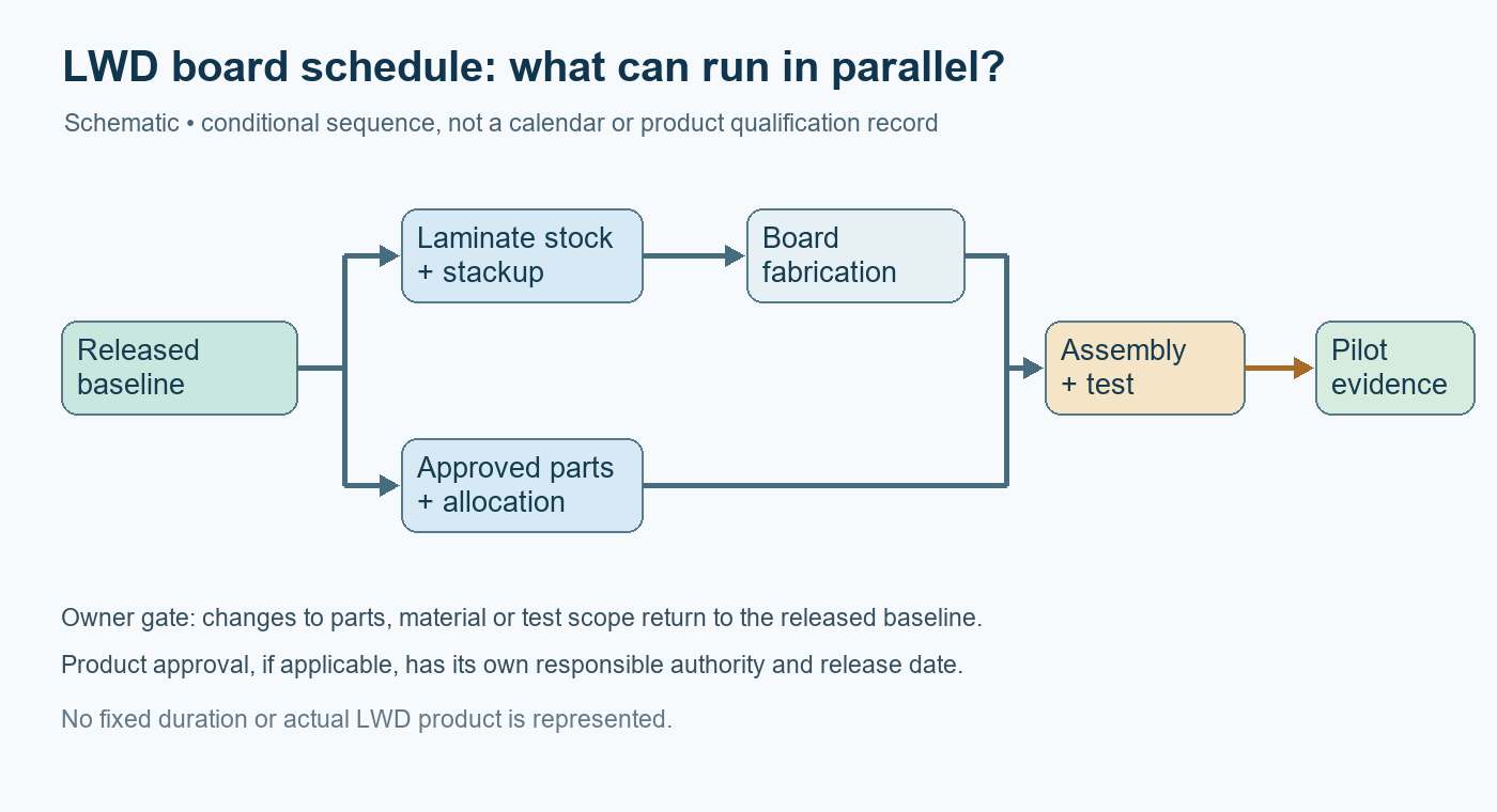
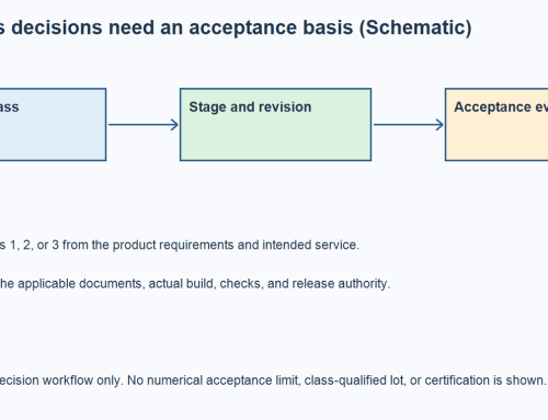
An LWD sensor-board lead time is the date at which the specified, tested configuration can be released—not simply the board fabricator’s quoted cycle. Logging while drilling (LWD) places measurement electronics in a bottomhole assembly, but it does not define one temperature, PCB stackup, component list, or approval route for every tool. Build the schedule from the released mission profile and a dated bill of materials (BOM). Then identify which component, laminate, test fixture, or product approval decision actually governs the next build. Ask each owner for evidence and a decision date. An estimated stock date, a high-Tg label, and an unreviewed substitute are not interchangeable with reserved parts and an approved design. The worksheet below separates the work that can run in parallel from decisions that must remain gated.
Define the release date before quoting a build cycle
SLB defines LWD as formation measurements made while drilling, with tools in the bottomhole assembly. That context can motivate environmental requirements, but the OEM must provide the actual operating and storage profiles, board location, duty cycle, loads, and acceptance limits. A supplier cannot derive those from the acronym. The requested date may mean a first assembled prototype, an environmentally tested pilot, or a configuration cleared for a particular market or installation. Put the milestone and evidence on the RFQ before comparing supplier lead times.
For each milestone, record the current revision, required quantity, accountable decision owner, predecessor, earliest committed date, and evidence still missing. The critical path is the longest chain of dependent work to that milestone; it can change when a part is allocated, an alternate is rejected, or a test fails. Board fabrication and component purchasing may overlap after their inputs are stable. Assembly cannot finish before the approved material set and fabrication data arrive. A product approval decision, when applicable, remains with the responsible product and assessment authorities rather than a PCB supplier’s generic quotation.
| Workstream | Evidence to request | Dependency or release gate | Owner’s decision |
|---|---|---|---|
| Mission and design baseline | Operating and storage profiles, schematic, stackup targets, revision-controlled BOM and drawing | Limits material and component choices before a reliable schedule can be set | OEM design authority freezes the build baseline or names open exceptions |
| Constrained components | Manufacturer part number, rating evidence, approved source, quoted and allocated quantity, dated supplier commitment | Longest unreserved approved part can govern assembly start | OEM approves an alternate, a partial build, or a revised milestone |
| PCB material and fabrication | Named laminate and properties, stock confirmation, proposed production stackup, fabrication exception list | Changing material or geometry may reopen design or environmental validation | OEM accepts the production structure and any deviation |
| Assembly and verification | Placement, profile constraints, inspection and functional-test plan, fixture readiness | Cannot claim a tested assembly until material, process and fixture inputs align | OEM and assembler agree pilot acceptance evidence |
| Product assessment, if required | Applicable approval basis, controlled configuration, change disposition and assessment schedule | A changed component or board revision may need review before product release | Responsible approval authority determines the route and release |
The entries describe questions, not standard durations. Obtain actual dates from named suppliers for the current revision, quantity and destination. The existing component-shortage guidance explains why alternate sourcing requires controlled review; here the schedule must show precisely which approval is pending.
Qualify the complete high-temperature parts chain
Do not use a single headline temperature for a board. A downhole mission may have a peak exposure, continuous exposure, storage condition, thermal cycling and local self-heating; the OEM must state which limits apply at each component and interface. Analog Devices’ high-temperature design review explains that silicon, packages, interconnects, solder and PCB materials can impose different constraints, and that application validation extends beyond an isolated data-sheet number. Its examples are not a rating for an unknown LWD assembly.
Check the selected sensor, analog front end, processor, memory, passives, connector, cable termination, joining materials and protection devices against the relevant mission profile. Record the exact manufacturer part number, grade, datasheet condition, approved substitute list and available source. Where the environment exceeds a published component condition, the design owner must establish a defensible qualification route; procurement should not translate a brief temperature excursion into a continuous-life claim. A board may be delayed by a connector or adhesive even when the IC and laminate are in stock.
Supplier dates need an evidence label. Texas Instruments describes future inventory dates as estimates that can change. Distinguish a website estimate from a written allocation or accepted order covering the exact approved part and quantity. Keep a dated sourcing log showing supplier, manufacturer part number, traceability requirement, quantity, date basis and the owner of any alternate decision. This prevents an optimistic stock screen from silently becoming the project completion date.
If the BOM is still open, an OEM can share the revision-controlled BOM and temperature profile for a sourcing review, alongside quantities and target build dates. OrinewPCB can evaluate component availability and assembly assumptions for a quotation; the OEM remains responsible for part suitability and design approval.
Treat Tg as one laminate property, not a field rating
The glass-transition temperature, Tg, is useful for comparing laminate behavior through a thermal transition. It is not a standalone promise that a populated board will survive an LWD mission. Isola’s material guidance considers thermal reliability through multiple attributes. The board specification also needs the applicable dielectric and copper construction, thermal expansion, decomposition and moisture behavior, plus the fabrication and assembly cycles the material must tolerate. The OEM should define the service exposure and reliability evidence to be assessed against the chosen material.
OrinewPCB’s short High-Tg versus standard FR-4 video is an AI-generated explanation of when Tg enters a material discussion. It is not a test of this LWD board or proof of its temperature rating. A laminate substitution may affect stackup, impedance, drill and plating processes, availability and an assessed product configuration. Confirm stock and production geometry before accepting a shorter fabrication quote.
The Tg comparison guide gives additional material-selection context. For this schedule, the actionable question is whether the approved laminate and stackup are actually available for the order, and whether a proposed faster alternative reopens design validation.
Parallelize preparation without crossing approval gates
Some work can start before every part arrives: resolve fabrication queries, prepare stencil and placement data, check assembly-process constraints, draft inspection criteria, book test resources, and review the fixture interface. Only count such work as schedule savings if its inputs are stable. A new footprint, connector, laminate thickness, thermal process or cable can invalidate work prepared against a prior revision. The PCB assembly process overview places component readiness, fabrication, assembly and testing in sequence; the project schedule should add revision and decision gates at each handoff.
Use two dates for every proposed acceleration: the earliest technical start and the latest reversible stop. For example, a fabricator may review the stackup while purchasing seeks allocation, but a production panel should not be released on an unapproved material deviation. A fixture can be designed from an approved interface drawing while purchase orders proceed, but its final build should reflect the released connector and test limits. This separates harmless parallel engineering from speculative inventory or tooling cost.
For a prototype, a partial build may expose assembly or firmware issues earlier. It is a distinct configuration with its own BOM, serial or lot traceability, and limitations. State which unavailable parts are simulated or omitted and which tests remain invalid. A successful partial bring-up is not evidence that the final temperature, intrinsic-safety or environmental requirements have been met.
Keep any protection assessment on its own schedule
Intrinsic safety is not a default property of every LWD board. If the intended product or installation has an applicable protection requirement, the OEM and its responsible assessor must identify the standard, assessed configuration, change-control boundaries and approval milestone. The public scope of IEC 60079-11 concerns intrinsically safe and associated apparatus; that fact alone does not establish which certificate, if any, applies to this design. The telemetry PCBA handoff guide discusses how to carry the controlled configuration into manufacturing.
A component alternate or board material swap can be electrically plausible yet still require assessment under the project’s approval basis. Keep the production schedule and approval schedule separate, with an explicit dependency where one cannot close before the other. Request the responsible authority’s disposition before booking a product-release date. Do not present a supplier’s PCB fabrication or inspection record as a certification result.
Request a schedule that can be audited
Send the same package to every bidder: released fabrication and assembly data, revision-controlled BOM with approved alternates, mission and storage profiles, quantities and split-build allowance, inspection and test requirements, fixtures, traceability, destination, and the desired milestone definition. Ask for a critical-path schedule, dated material commitments, open assumptions, decision owners and exception-response deadlines. Quotations that assume different parts, test scope or approval milestones are not comparable lead-time offers.
At weekly review, update the actual dates and evidence rather than reporting a single optimistic “weeks to go” number. A practical status row reads: approved part / quantity / source commitment / planned receipt / next gate / owner / evidence link. Apply the same pattern to laminate, PCB fabrication, assembly, test and product assessment. Escalate only the decision that changes the critical path; a late noncritical task may need attention without moving the release date.
The practical conclusion is a controlled critical path: reserve and approve the exact parts and material, run stable preparation in parallel, and leave design and product-release gates with their accountable owners. For a coordinated build, the full-turnkey assembly service provides the relevant fabrication, sourcing and assembly context. When the baseline is ready, send the released fabrication and assembly package with the dated BOM, test scope, milestone and known approval holds so the team can review material constraints and quote the same deliverable. The OEM still controls the environmental limits and any required protection release.
Latest Blog


Contact Info
Phone: +86-755-82882936
Email: [email protected]
WhatsApp: +86-13570802455
Wechat: +86-13570802455
Address: 2nd floor,D Bldg.,Electric Link Technology Bldg.,Gongming,Guangming New Dist.,518106 Shenzhen, China