
Airborne Weather Radar Processor PCB: A Manufacturing Handover Pack
Table of Conent
Table of Conent
A weather-radar processor PCB is ready for manufacturing transfer when the design authority can identify one approved hardware baseline and show a supplier exactly how to build, inspect, program, and report against it. The handover needs more than Gerbers and a parts list: it needs controlled fabrication data, assembly and programming instructions, component substitution rules, test access and limits, revision identifiers, and a path for nonconformances. Define the processor board’s actual system boundary first. A digital signal-processing assembly, an RF front end, and a combined board impose different stackup, shielding, and test requirements; the phrase “radar PCB” does not specify which one is being purchased. Keep manufacturing acceptance separate from airborne equipment design assurance, environmental qualification, and approval. The OEM or applicant sets the applicable program requirements and accepts design changes. The fabricator and assembler can supply the contracted build and test records, but a passing PCB lot alone cannot establish that the radar equipment is approved for flight.
Fix the board boundary and approval owner
Start the transfer with a block diagram that names the assembly’s real interfaces and the authority for each requirement. A weather-radar processor may receive digitized data from another unit, include conversion and RF circuitry, or combine functions. Do not infer an X-band laminate, a particular FPGA, or a radar-detection claim from the article topic. For the actual design, identify clocks, high-speed serial links, power rails, aircraft or display interfaces, connectors, shielding, cooling path, and any software or programmable-logic loading responsibility. The released schematic, layout, and interface-control documents should agree on each item.
The OEM or applicant should state the program’s certification basis, intended function, safety allocation, and design-assurance responsibilities. The manufacturer should accept only the build, inspection, programming, and test scope written into the purchase package. FAA AC 20-152A (October 2022) discusses development assurance for airborne electronic hardware and includes circuit board assembly objectives. It describes an acceptable means, not the only means, for showing compliance in the applicable approval context. FAA AC 00-72 supplies complementary best-practice discussion. Neither advisory circular turns a generic board inspection report into a flight approval.
Set a document hierarchy before the first supplier review: released requirements and interface definitions, controlled board and assembly drawings, approved component and process baselines, then the records that demonstrate conformance. Name who can approve a material substitution or a test-limit change. A supplier can recommend an alternative, but the design authority decides whether it preserves the intended function and whether additional verification is required. This is a practical boundary for the entire handover, not a claim that OrinewPCB holds an aerospace approval.
Transfer fabrication constraints as controlled data
Fabrication data must specify the electrical and physical constraints that the image files alone cannot express. Provide the released native or agreed manufacturing output files, drill and route data, board outline, revision, stackup, dielectric construction and materials, copper weights, controlled-impedance structures and their reference conditions, via construction, surface finish, marking, and any special coupon or sectioning plan. State the permitted material alternatives rather than leaving a named laminate to stand in for a qualified construction. Let the fabricator document proposed stackup deviations before CAM release.
IPC-6012F (September 2023) defines qualification and performance requirements for rigid printed boards across several constructions. The applicable performance class, revision, addenda, and customer deviations need to be called up in procurement documents; the standard name alone does not identify the radar program’s acceptance rules. For dense processor packages, map BGA escape, via structures, and coupon placement to an approved construction. Our HDI BGA escape release guide explains how package geometry and microvia design affect the build review.
Ask the board fabricator for the records that correspond to the specified constraints: final stackup, impedance coupon results where required, material and process traceability, dimensional and visual inspection, electrical test, and approved deviations. The exact test method, sampling, units, and acceptance limits must come from the controlled purchase package. A note that merely says “impedance controlled” leaves open the target geometry, reference layer, measurement conditions, and disposition for a failure. A PCB DFM report review should close fabrication exceptions before the final data set is frozen.
| Released item | Design or procurement owner | Supplier record to request | Release decision |
|---|---|---|---|
| Board construction, impedance and via design | OEM hardware/design authority | Final stackup, approved CAM exceptions, coupon or inspection results under the specified method | Does this lot match the approved physical and electrical baseline? |
| BOM, placement, polarity and programmed image | OEM controls revision and alternates; assembler controls execution records | Material trace, build traveler, inspection and load/version record if programming is in scope | Was this exact approved configuration assembled and recorded? |
| Functional interfaces and production-test limits | OEM defines behavior, fixture, limits and disposition | Fixture revision, calibration status where applicable, per-unit results and exceptions | Does measured evidence cover the contracted acceptance scope? |
| Environmental or equipment qualification | Applicant or equipment owner | Only expressly contracted supporting records | What further equipment-level evaluation remains outside PCBA lot acceptance? |
Release the assembly and programmed-device baseline
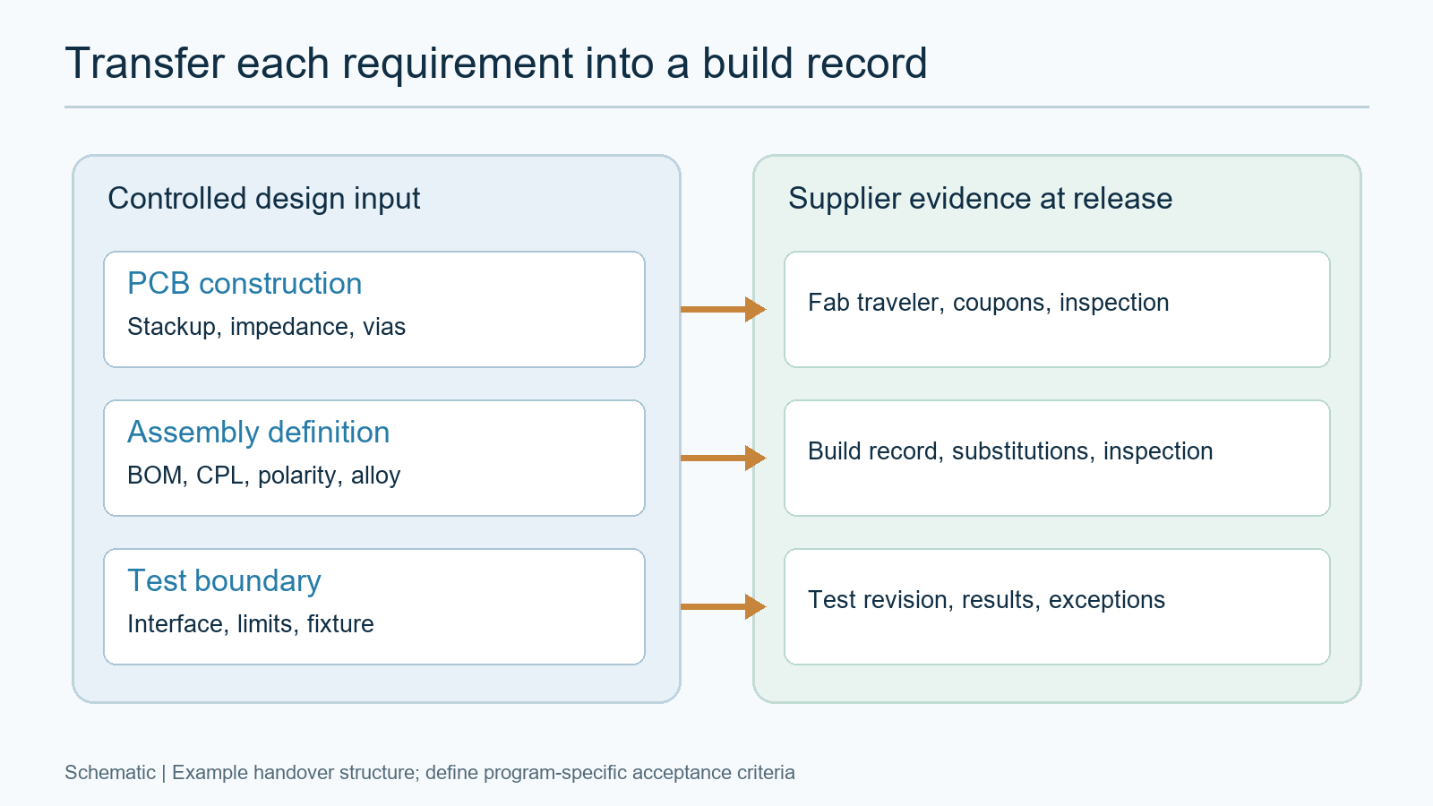
The assembler needs a configuration it can build and repeat, not just a BOM export. Supply the assembly drawing, pick-and-place or centroid data, component orientations, approved manufacturer part numbers, alternates and substitution authority, solder alloy, process-sensitive parts, coating or cleaning instructions if required, and the revision of every programmed-device image. If component traceability, moisture handling, or lot segregation is required, state the level and retention period contractually rather than assuming a shop’s default traveler is sufficient.
If the approved fabrication data, BOM and loading ownership are defined, share the controlled board and assembly package for review. Include the board revision, component alternates policy, placement data, quantities and proposed inspection or programming scope so the fabrication and assembly assumptions can be checked together before a production price is finalized.
Separate three often-confused configurations: the bare-board revision, the populated assembly revision, and the version of any firmware or programmable logic loaded during production. The equipment owner controls functional behavior and approval of a new image. The assembler may execute the approved load procedure and record the image identifier, but that record does not validate the software or hardware design. If programming will happen elsewhere, write that exclusion explicitly so an unprogrammed board is not mistaken for a ready-to-install unit.
The first build should include a joint review of component availability, BGA process assumptions, stencil and reflow constraints, connector support, inspection access, and rework limits. A late approved alternate can change electrical behavior, thermal loading, mechanical fit or test coverage. Treat the alternate as a controlled change, not a purchasing convenience. The drawing, BOM, supplier quotation, and test procedure must all point to the same revision set.
Make every acceptance test traceable to a requirement
A test is useful only when it measures an identified board-level requirement under a named configuration. For each power rail, digital interface, clock, memory or processor function, connector path, and fault indication that is in production scope, state a test method, fixture or software revision, limit, conditions, unit of measure and pass/fail owner. Define what a board-level test cannot establish. A PCBA can pass continuity, current draw, interface or programmed self-test without proving the radar’s detection performance in the aircraft installation.
Map design requirements to test methods before placement data and panelization are frozen. Probe access, fixture keep-outs, programming connectors, and serialization are physical design choices. Our PCB test-planning guide gives a general requirement-to-method-to-record framework. For a weather-radar processor, add the program-specific interface conditions and record whether the data path is simulated, connected to a known source, or exercised as part of the complete equipment. Label an illustrative bench setup as an example; never pass it off as a certified radar test.
Environmental qualification is a separate layer. RTCA DO-160 describes environmental conditions and test procedures for airborne equipment; applicable categories and pass criteria come from the equipment program. A component or board-level screening operation does not automatically satisfy equipment-level environmental qualification. Use a controlled boundary table to say who owns vibration, temperature, power-input and electromagnetic test plans, what unit is tested, and how failures feed back to the PCB design. Our PCB assembly environmental-test selection guide addresses the narrower assembly-screening decision.
Plan first-article evidence and changes before production
Decide what makes the first build representative before placing the order. The OEM and supplier should agree on the approved data revision, quantity, process route, inspection points, test records, nonconformance disposition, and the point at which an altered process or component requires a fresh review. If the contract invokes SAE AS9145, its aerospace APQP and PPAP framework informs production planning and product/process validation. Do not claim every radar processor order is automatically governed by AS9145, or that an ordinary first-board inspection alone fulfills a program’s PPAP package.
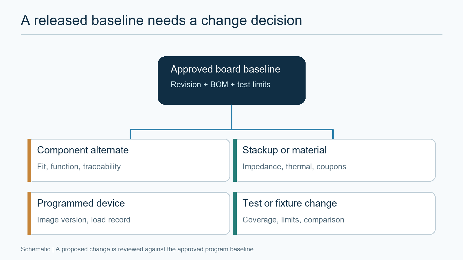
In the first-article review, compare the actual board construction and assembly configuration with the released baseline. Resolve open DFM exceptions, approved alternates, programming records, and test-fixture revisions before calling the evidence complete. Any nonconforming result needs a documented disposition owner and, where required, design-authority approval. Production should not quietly substitute a new stackup or device to preserve a delivery date.
| Proposed change | Possible affected evidence | Decision before use |
|---|---|---|
| Component alternate or obsolescence replacement | Fit, power, timing, temperature, traceability, assembly process and functional tests | Design authority approves equivalence and defines any repeat tests. |
| Laminate, stackup, via or fabrication-site change | Impedance, thermal path, reliability coupons and fabrication inspection | Owner evaluates construction data, coupons and qualification impact. |
| Firmware, FPGA image or programming-route change | Load record, functional behavior and production-test coverage | Equipment owner controls image approval; supplier follows the released load process. |
| Test fixture, software or acceptance-limit change | Measurement comparability, calibration and historical pass/fail meaning | Approve new revision and decide whether earlier units require retest. |
Send one controlled package for PCB assembly review
A useful RFQ package tells the supplier what to price and what evidence to return, while reserving equipment approval to the responsible program. Provide the controlled fabrication data and stackup, assembly drawing and placement data, approved BOM and alternates policy, programming ownership, target quantity, build and inspection class as invoked, test methods and limits, traceability requirements, and any contractually required first-article or environmental support records. Include a change and deviation contact. Keep export-control or other controlled-data handling requirements explicit when they apply; do not assume an ordinary quote portal is automatically authorized for restricted files.
A full-turnkey PCB assembly scope can align board fabrication, parts sourcing, assembly and specified test around one configuration for review. That is a manufacturing-service scope, not a representation that the supplier certifies an airborne radar system. The design authority should retain the functional requirements, certification plan, equipment environmental categories and final acceptance decision. For a project ready for manufacturing review, send the released build and test package for evaluation with the revision-controlled files, quantities, BOM, interface and test scope, and required supplier records. The subsequent quote can identify fabrication, sourcing, assembly, testing and unresolved approval assumptions before either side commits to a build.
Latest Blog


Contact Info
Phone: +86-755-82882936
Email: [email protected]
WhatsApp: +86-13570802455
Wechat: +86-13570802455
Address: 2nd floor,D Bldg.,Electric Link Technology Bldg.,Gongming,Guangming New Dist.,518106 Shenzhen, China