
Environmental Testing for PCB Assemblies: Choose Humidity, Vibration, and Salt Exposure
Table of Conent
Table of Conent
Choose environmental tests for a PCB assembly from the failure mechanisms in its actual installation, not from a generic chamber menu. Sustained damp heat can expose leakage and corrosion risks, vibration can reveal intermittent connectors or fatigued solder joints, and salt exposure is relevant when a credible salt-laden path reaches the product. The test method, severity, operating state, sample configuration, and pass criteria must be specified together. A board that passes one chamber exposure is not automatically qualified for another environment or for a promised field life.
This guide helps an OEM engineer or buyer turn a field-risk statement into a test request and a comparable PCBA quotation. It separates design qualification from production screening, and it treats the enclosure, harness, coating, firmware, and board revision as part of the test article where they affect the result.
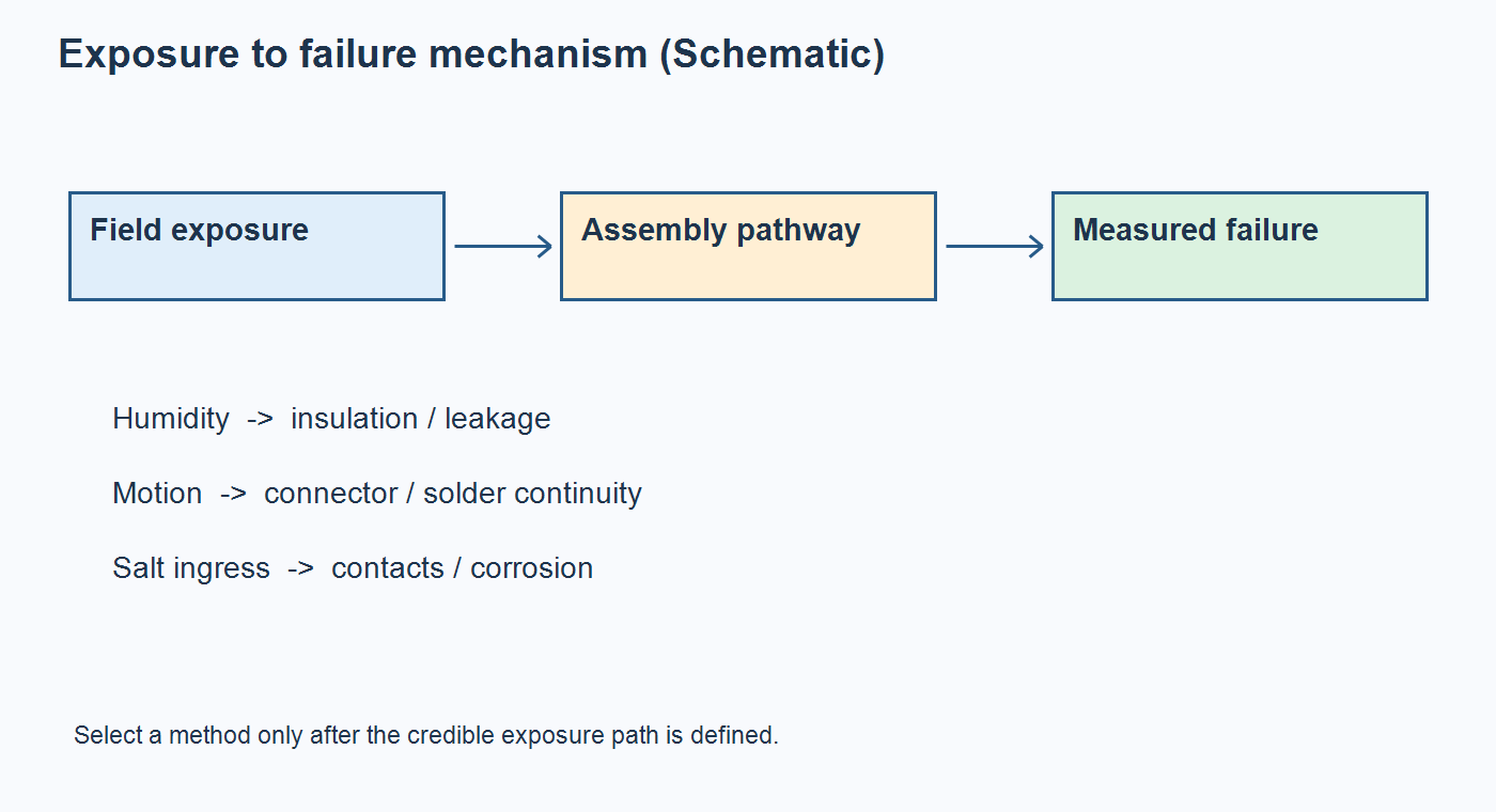
Start with the exposure path and the failure you need to detect
The first decision is which stress can actually reach the electronics. A sealed indoor controller, a vehicle-mounted module, and equipment near marine spray do not need the same default test package. Record where the product is installed, whether the enclosure is open or sealed, operating and storage conditions, condensation and washdown risk, mounting orientation, transport profile, and service life objective. Distinguish a board-level exposure from a system-level one: a bare board in salt fog may create a failure path that does not exist inside the released enclosure.
Then name the expected failure: insulation resistance loss, leakage under bias, connector corrosion, cracked solder joint, intermittent communication, fastener loosening, or post-exposure functional drift. The failure statement determines where to measure and whether the assembly must be powered. For internal laminate migration under heat, humidity, and bias, the CAF test plan is a more specific path than a broad damp-heat exposure.
Match the method to the question, not the chamber name
Humidity, vibration, and salt methods answer different questions. IEC 60068-2-78:2025 describes steady damp heat at constant temperature without condensation; it should not be described as a condensation-cycle test. IEC 60068-2-6:2007 addresses specified sinusoidal vibration. IEC 60068-2-64:2026 addresses broadband random vibration and accumulated dynamic-stress effects. IEC 60068-2-52:2017 covers cyclic salt mist for components or equipment intended for a salt-laden atmosphere. These documents define methods, while the product specification still has to choose an applicable severity and acceptance criteria.
| Credible risk | Useful test question | Configuration and measurement to specify | Decision after test |
|---|---|---|---|
| Sustained warm humidity without expected condensation | Does insulation, coating, or function degrade during damp-heat exposure? | Define temperature, relative humidity, duration, bias and operating state; measure baseline, in-exposure values if feasible, and recovery. | Accept only against defined electrical and visual limits; investigate leakage or drift by location and revision. |
| Periodic motor or transport motion | Does the released assembly remain mechanically and electrically sound under the relevant spectrum? | Define sine or random method, spectrum, axes, fixture, mounting torque, harness restraint, operating state, and intermittent-event monitoring. | Review connector continuity, solder and hardware condition, and functional logs; change the mount or retention design if evidence points there. |
| Credible salt-laden ingress or exposed metal | Does the chosen coating, finish, connector, or enclosure path tolerate the specified salt exposure? | Define exposed specimen, preconditioning, salt method, cycle or duration, rinse/recovery, and corrosion plus function criteria. | Compare only like-for-like specimens and criteria; a chamber duration alone is not a field-life claim. |
Methods can be combined when risks interact, but sequence matters. Damp heat before vibration may alter joints or coatings; vibration before salt exposure may disturb seals. If sequence is a product requirement, lock it in the plan and preserve intermediate measurements. A standalone environmental test on a coupon, a bare PCBA, and a housed product are different evidence classes.
Humidity: specify bias, condensation, and recovery
A steady damp-heat result is meaningful only for the tested construction and electrical state. Record conductor spacing and voltage, board cleanliness, coating or potting, connector materials, ventilation, and whether the assembly is energized. A bias-free chamber exposure may miss an electrochemical mechanism that requires voltage. Conversely, a highly accelerated biased test vehicle is not proof of the calendar life of an enclosed product.
Measure sensitive functions before exposure, during exposure where the setup permits, immediately afterward, and after a defined recovery interval. Leakage and sensor drift can disappear after drying, so a dry final functional test alone may hide the mechanism. Separate surface contamination from internal laminate risk. The ionic cleanliness testing guide explains why an extract result and a localized residue investigation answer different manufacturing questions.
Do not describe every moisture failure as a coating defect. Enclosure ingress, cable wicking, trapped process residue, insufficient drying before coating, and biased conductor geometry can all matter. If a coating is selected, define coverage and masking, inspection points, repair method, and its compatibility with connectors and service access. The coating versus potting comparison shows why protection should follow the exposure and maintenance model.
Vibration: test the installed assembly, including its cable load
Mechanical stress enters through the mounting system. Match the fixture to the intended mounting points, torque, standoffs, enclosure and cable restraint; otherwise the test may excite an artificial resonance. Choose a sine method when the requirement targets defined frequencies or resonances, and a random method when the field profile is stochastic and the governing specification calls for it. Neither method should be assigned a convenient universal amplitude.
Monitor critical functions while the unit moves. A connector can open for milliseconds and look normal during a post-test bench check. Log communication errors, reset counts, voltage interruptions, sensor outputs, and any failure state that matters to the product. Document axes, exposure duration, acceleration or displacement definition, control location, fixture response, and interruptions. If a high-mass component or cable pulls on the PCB, examine mechanical support and solder-joint strain before adding a stronger test.

Inspection is a baseline, not a substitute for in-test functional monitoring. Link photographs, AOI findings, continuity records, and failure logs to each sample serial number. Repeatedly passing room-temperature functional test after vibration cannot exclude brief in-test contact loss.
Before ordering fixtures and samples, share the mounting drawing, harness restraint, operating modes, and proposed monitoring points. A fabrication and assembly review can identify fixture access, connector retention, and test-point changes while the design is still editable.
Salt exposure: define the exposed article and avoid a lifetime shortcut
Salt mist belongs in the plan when the installation can plausibly expose the relevant surfaces or enclosure joints to a saline atmosphere. Decide whether the test article is a plated coupon, connector, bare PCBA, coated assembly, or complete product. A connector exposed without its normal seal may support material screening, but it should not be reported as qualification of the assembled enclosure.
IEC 60068-2-52:2017 provides a cyclic salt-mist method for equipment intended for salt-laden atmospheres. ASTM B117-26 defines a controlled salt-fog apparatus and procedure; ASTM explicitly cautions that stand-alone salt-spray results seldom predict performance in natural environments and does not prescribe a product-specific exposure period. A number of hours in either test must therefore be tied to a governing product requirement, specimen, method, inspection interval, and acceptance limit—not converted into years of field life.
Ask whether the customer needs visual corrosion limits, contact resistance, insulation resistance, coating adhesion, sealing integrity, or full functional operation after recovery. Record rinsing and cleaning instructions, because post-test handling can change the observed result. When production residues could drive a failure, preserve control samples and avoid cleaning away the evidence before root-cause analysis.
Release one controlled test package and quote its boundaries
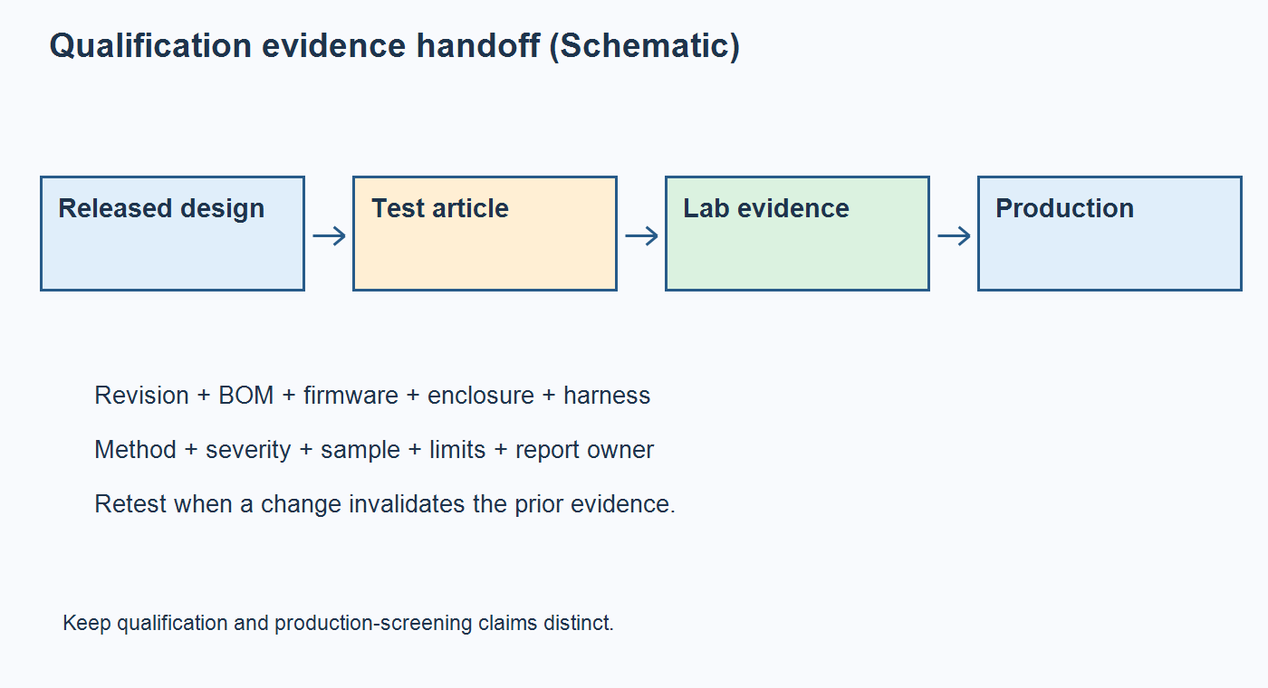
A useful environmental-test request contains the product mission profile, revision-controlled schematic and PCB files, BOM with approved alternates, assembly and enclosure drawings, firmware version, mounting and harness details, test methods and severities, sample quantity, operating modes, measurements, acceptance criteria, reporting format, and failure disposition owner. Mark which items are supplied by the OEM, assembler, and independent laboratory. Laboratory qualification, production functional screening, and recurring inspection should be separate quoted lines.
If a design or material changes after qualification, apply the DVT change-review method to identify which evidence is still valid. A new connector plating, coating, mounting bracket, board laminate, cleaning process, or firmware monitoring rule can invalidate a prior result even when the circuit diagram looks similar.
For a complete project, the full turnkey PCB assembly scope provides a commercial starting point for fabrication, component sourcing, assembly, and defined test work. Confirm separately who supplies environmental chambers, fixtures, calibration, sample builds, failure analysis, and formal approval; none of these should be assumed from an assembly quote alone.
Conclusion: qualify the failure path you can defend
Humidity, vibration, and salt exposure are not interchangeable reliability badges. Select each method from a credible field pathway, control the test article and its revision, measure the failure during the relevant stress, and set pass criteria before the chamber run. Keep standard-method compliance, design qualification, and production screening as distinct claims. This gives engineering and purchasing a basis for comparing evidence and the true delivered cost of a tested PCB assembly.
When the test matrix is ready, submit the controlled PCB files, BOM, quantities, enclosure and harness details, and acceptance limits for a combined assembly review. The team can then clarify manufacturing scope, test ownership, and quotation assumptions against the same released configuration.
Method references
- IEC 60068-2-78:2025, steady damp heat — scope and noncondensing method.
- IEC 60068-2-6:2007, sinusoidal vibration — method and reporting scope.
- IEC 60068-2-64:2026, broadband random vibration — dynamic-stress method.
- IEC 60068-2-52:2017, cyclic salt mist — salt-laden equipment method.
- ASTM B117-26, salt-spray apparatus — scope and field-correlation limitation.
Latest Blog


Contact Info
Phone: +86-755-82882936
Email: [email protected]
WhatsApp: +86-13570802455
Wechat: +86-13570802455
Address: 2nd floor,D Bldg.,Electric Link Technology Bldg.,Gongming,Guangming New Dist.,518106 Shenzhen, China