
Checkweigher PCB Reliability: Test Precision Signals Under Conveyor Vibration

Table of Conent
Table of Conent
A reliable checkweigher PCB is one that preserves the load-cell signal, produces repeatable digital measurements, and exposes enough diagnostic data to distinguish an electrical fault from a vibrating conveyor. Test the assembled board first with a stable, documented input; then test the installed machine with its actual sensor, cabling, motor states, product and line speed. A board that passes a bench measurement can still yield poor dynamic weights when the weighing conveyor is mechanically coupled to neighboring equipment. Conversely, unstable ADC codes with a stable input point back toward the board, its power, reference, connector or firmware. The acceptance limit must come from the checkweigher OEM’s product and application requirements, not from a generic PCB test checklist.
This distinction matters to an OEM releasing a design and to a buyer specifying PCBA tests. The METTLER TOLEDO checkweighing guide identifies vibration, electrical noise, repeatability and re-zeroing as commissioning concerns. The board supplier can inspect and electrically exercise the PCBA, but the installed machine must be evaluated under the conditions in which it will weigh products.
Separate the weighing chain from the conveyor
Start with the signal path and identify where a disturbance can enter. In a strain-gauge design, a load-cell bridge produces a small differential signal that travels through a connector and cable to the board’s input filtering, amplification or ADC. The digital output is then interpreted by firmware. Some checkweighers use other sensor architectures, so the released schematic and sensor specification—not a generic drawing—control the actual test points.
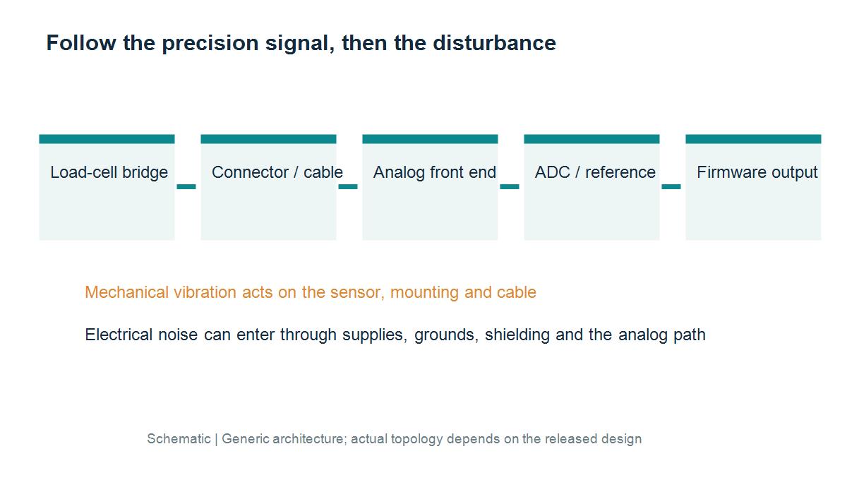
For a bridge-based circuit, record the excitation and ADC reference topology before choosing a noise test. Analog Devices’ AN-2505 weigh-scale example explains how sense wires, a ratiometric reference, supply filtering and ground noise affect a low-level measurement. Its component values and example load cell are design-specific; they are not universal checkweigher limits. If the board uses a different sensor, front end or reference architecture, the same diagnostic principle applies but the measurements and fixture must change.
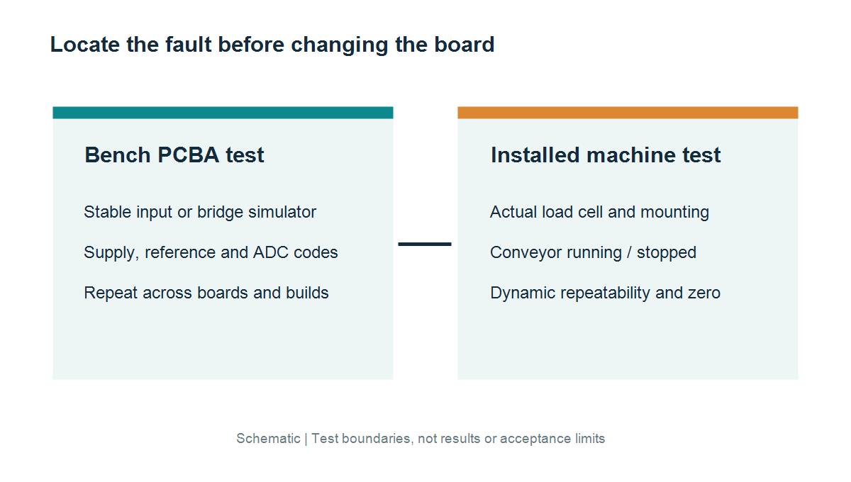
Use a stable input or a suitable bridge simulator at the board boundary, then capture raw ADC codes, calculated weight, excitation and reference behavior. Compare stationary and motor-on states without changing the input. If the readings shift only when a motor or drive runs, investigate power, grounding, cable routing, shielding and EMI before changing calibration constants. A related industrial sensor grounding and EMI discussion shows why the complete cable and enclosure path belongs in the review. A neighboring load-cell and servo-noise example covers another packaging-machine application; its noise mechanisms are useful analogies, not a substitute for this checkweigher’s measurements.
Bench-test the signal before blaming the conveyor
A staged bench test is the fastest way to decide whether a PCBA fault is plausible. Verify the assembly revision, firmware build, input fixture and supply conditions first. With a fixed, traceable input, compare zero, span points and repeated readings across boards. Preserve both the raw counts and the processed weight so a filtering or calibration change is distinguishable from analog drift. No single sample proves repeatability; the sample count and acceptance interval should be specified by the OEM for the intended product range.
Test the measurement path under the electrical states the machine will actually create: startup, a running conveyor drive, reject-actuator operation and any relevant communications activity. Log the timing of a disturbance alongside the ADC output. This is an engineering diagnostic, not a claim that every motor must be powered during every supplier production test. Decide whether the production fixture reproduces those states or whether they remain an OEM integration test.
Analog Devices’ radiated-immunity study tested a complete weigh-scale circuit and load cell while monitoring conversion deviation; it also shows that layout, grounding, filter location and component placement can change susceptibility. Its setup and performance target belong to that example circuit. Use the applicable equipment standard and the OEM’s agreed performance criterion for this machine. More generally, choose environmental and electrical tests from actual field exposures rather than stacking every possible test onto the purchase order.
When the bench response is unstable with a stable input, preserve the failing board, fixture setup and waveform or ADC log before rework. If the board is stable on the bench, avoid redesigning the analog front end merely because installed weights vary. For a prototype or pilot build where that distinction is still unresolved, an OEM can share the schematic, BOM and proposed bench-test fixture for review so assembly and functional-test scope can be priced against the actual design.
Repeat the test on the installed, running machine
Installed-machine repeatability is a separate acceptance gate. Use the actual load cell, mounting, cable length, conveyor geometry, product presentation and operating speed. Record the same test items under conveyor stopped and conveyor running conditions. If performance changes only when the conveyor runs, check mechanical contact, belt tracking, nearby equipment coupling and load-cell mounting before assigning the problem to the PCB. METTLER TOLEDO specifically calls for vibration control and on-site repeatability and re-zero checks during commissioning.
| Observation under controlled conditions | First diagnostic action | Likely owner of the next test |
|---|---|---|
| Stable simulator input; raw ADC codes wander with conveyor drive on | Measure board supply and reference; inspect shield return, grounding, cable route and motor-state timing | OEM electronics with PCBA supplier support |
| Stable bench codes; installed weight spread increases when conveyor runs | Compare stopped/running results and inspect mounting, belt contact, vibration transfer and sensor cable strain | Machine OEM and integration team |
| Raw codes stable; calculated weight changes after firmware or recipe change | Restore controlled firmware and calibration record; compare filter, tare and conversion settings | OEM firmware and validation team |
| One board differs from the same controlled build and fixture | Preserve serial number, BOM lot, inspection record and functional log; compare assembly and component evidence | PCBA supplier and OEM quality team |
The table is a fault-isolation starting point, not a definitive diagnosis. For example, a cable that moves with the conveyor can cause both a mechanical strain effect and an electrical connection problem. A sensible test plan changes one variable at a time and retains enough raw data to repeat the finding.
Do not confuse assembly inspection with measurement proof
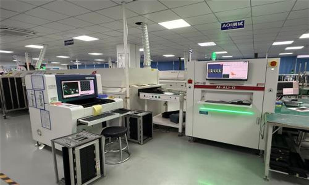
Optical inspection can catch visible placement and solder issues, but it does not demonstrate low-noise conversion, EMI immunity or dynamic weighing repeatability. Use incoming component control and assembly inspection to protect the build, then add a functional test that exercises the measurement path. The image below shows real factory AOI equipment; it is not a checkweigher line or evidence that a particular board passed testing.
A supplier’s record should connect the board serial or lot, assembly revision, firmware/configuration, fixture version, test input and pass criteria. Where a test is performed by the OEM after assembly, mark it as such rather than implying the PCBA supplier certified the complete machine. The PCB test planning guide provides a useful framework for defining method and record fields. A full-turnkey assembly service can coordinate parts and build scope, but its service description does not replace the project’s released test specification.
Release one acceptance package for the build
The purchase order should name each gate, its owner and the evidence required. A generic “100% tested” line is too ambiguous for a precision instrument. The OEM should release the sensor interface, measurement range, firmware version, calibration method and actual acceptance limits. The board supplier can then quote the fixture and repeatable electrical checks, while the OEM retains responsibility for line-level dynamic performance.
| Gate | Evidence to request | Decision it supports |
|---|---|---|
| Assembly release | Controlled fabrication files, BOM/approved alternates, assembly drawing and inspection criteria | Was the intended hardware built? |
| PCBA functional test | Fixture revision, stable-input points, raw/processed reading logs, supply/reference checks and firmware ID | Does this board reproduce the specified electrical response? |
| Electrical disturbance review | Applicable motor/drive and communications states, disturbance timing, defined pass criterion and retest record | Is the signal path susceptible under the agreed electrical conditions? |
| Installed-machine validation | Sensor and cable configuration, conveyor speed, product/test-item runs, repeatability, zero and re-zero record | Does the complete checkweigher meet the OEM’s dynamic requirement? |
Keep the acceptance limit tied to the product, measurement range and applicable customer or regulatory requirements. Do not copy an ADC data-sheet resolution or another machine’s gram value into the PCBA drawing and call it accuracy. If the build package and test ownership are ready, the sourcing team can send the released fabrication, assembly and test package for evaluation, including Gerbers, BOM, placement data, assembly drawing, firmware configuration and agreed bench-test limits. The review can then identify what belongs in the PCBA quote and what remains an OEM machine-validation activity.
The practical reliability decision
Approve the PCBA only after a controlled stable-input test demonstrates the specified electrical behavior across the intended build, and approve the checkweigher only after the installed line passes its dynamic and re-zero requirements. When a result fails, compare raw electrical readings with conveyor state before changing the board or recalibrating the machine. This two-boundary approach gives engineers a reproducible fault path and gives buyers a test scope they can actually verify. For the separate cost and quote inputs, see the checkweigher PCBA quotation guide.
Latest Blog

Contact Info
Phone: +86-755-82882936
Email: [email protected]
WhatsApp: +86-13570802455
Wechat: +86-13570802455
Address: 2nd floor,D Bldg.,Electric Link Technology Bldg.,Gongming,Guangming New Dist.,518106 Shenzhen, China